2: Introduction
EMG™ Edge Management Gateway User Guide
27
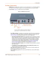
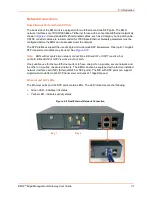
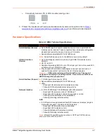
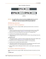
One Micro Secure Digital (micro SD) memory card slot
for use with micro SD card to collect
logs, save configurations, and update firmware. (Micro SD card provided by the user)
-
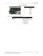
One digital IO (DIO) port
with two digital inputs and one relay output (terminal block) for
use with sensors
-
LED indicators
for ethernet port status and connectivity module status
Back Chassis:
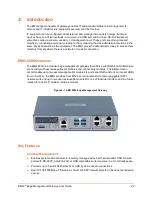
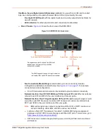
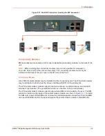
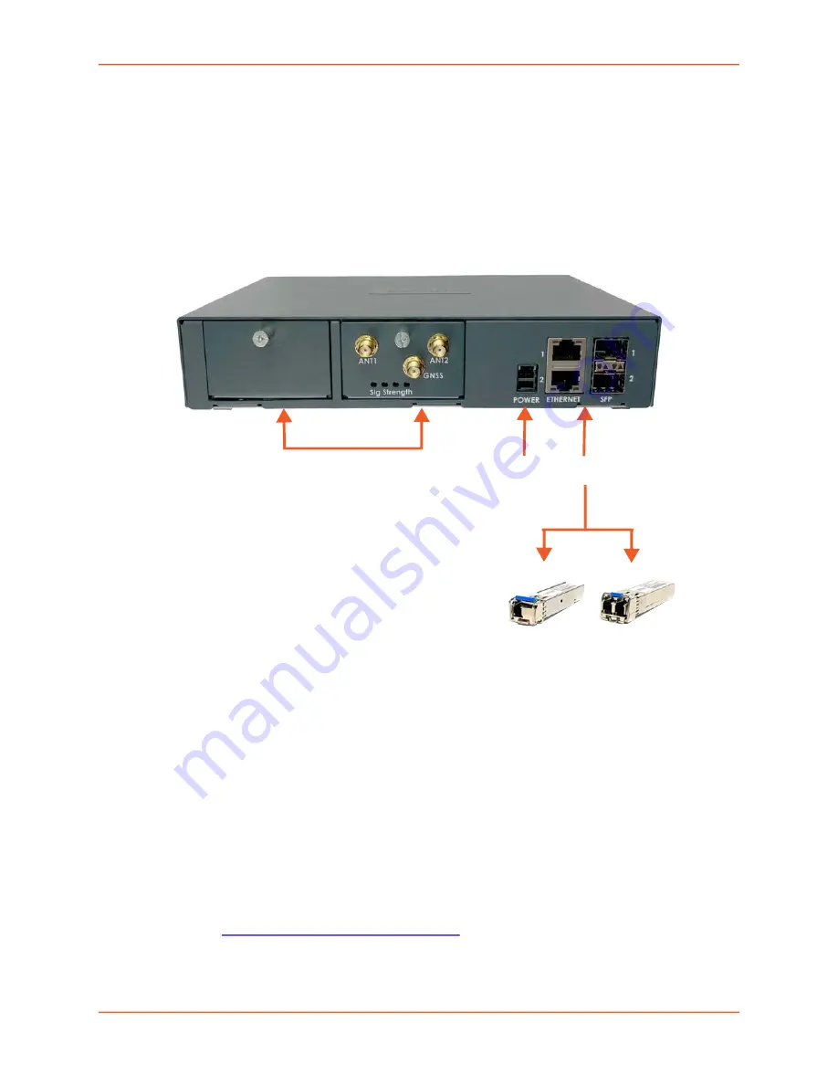
shows the back view of the EMG 8500:
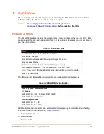
Figure 2-4 EMG 8500 Unit (back side)
-
Two Connectivity Module Bays
accommodate up to two connectivity modules.
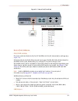
Configuration possibilities are listed below. See
for a sample
connectivity module configuration.
One LTE cellular modem module can be installed to provide cellular connectivity.
-
Network Interface:
Dual 10/100/1000 Base-T Ethernet port I/F card.
Ethernet ports are
referred to as Eth1 and Eth2 in the user interface and this user guide.
-
Network Interface:
Dual 1 Gigabit-capable SFP port I/F card
to support single or multi-
mode fiber optic SFP transceiver modules. SFP transceiver modules are referred to as
SFP1 and SFP2 in the user interface and this user guide.
Note:
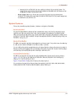
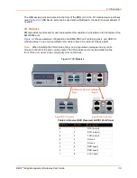
EMG will recognize two network connections. Either Eth1 or SFP1 is active, but
not both. Similarly, either Eth2 or SFP2 is active, but not both.
Lantronix offers SFP Transceivers (“modules”) for EMG 8500 edge management
gateways and SLC 8000 console managers with fiber SFP ports. To learn more, go to
https://www.lantronix.com/products/sfp/
SFP transceiver modules are provided by users according to fiber mode and brand
preferences.
The EMG supports the use of single mode and
multi-mode fiber optic SFP transceiver modules.
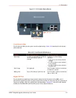
The appearance and function of the EMG will
depend upon the type(s) of the installed
connectivity modules.
Two Connectivity Module Bays
Dual Ethernet and
SFP Ports
Power inlet

