2-1
2: Installation
This chapter describes the various EPS models and shows how to install them into a basic
network situation.
2.1 EPS1/2 Product Description
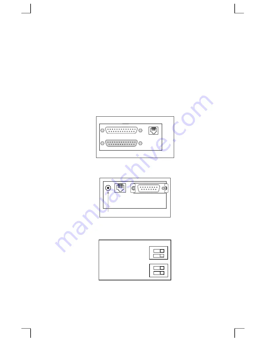
The front panel of the EPS has an RJ45 serial connector and either one (EPS1) or two
(EPS2) DB25 parallel connectors. The port names are Port_1 (serial), Port_2 (top
parallel), and Port_3 (bottom parallel, EPS2 only).
The back panel of the EPS has a power connector, an RJ45 Ethernet connector for
10BASE-T, and an AUI Ethernet connector.
The bottom of the EPS has a label noting the unit’s Ethernet address, needed for
configuration, and 4 DIP switches (explained in the Installation section).
The default name of the EPS is EPS_xxxxxx, where xxxxxx denotes the last 6 digits of
its Ethernet address.
Serial Port
Parallel Ports
1
2
3
AUI
RJ45
Power
Factory NVR / Normal
1 0
Silent Boot / Verbose
Option 3
AUI / 10BASE-T


