background image

Lantronix 


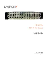
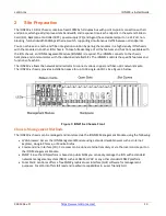
    ION219-x Install Guide 

33412 Rev. D 

https://www.lantronix.com/


 Warnings 

Warning

: Use of controls, adjustments, or the performance of procedures other than those specified herein may result in 

hazardous radiation exposure.  

Warning

: Visible and invisible laser radiation when open. 

Do not

 look into the beam or view the beam directly with optical 

instruments. Failure to observe this warning could result in an eye injury or blindness.  

Warning

:  DO NOT connect the power supply module to external power before installing it into the chassis. Failure to 

observe this warning could result in an electrical shock or death. 

Warning

: Select mounting bracket locations on the chassis that will keep the chassis balanced when mounted in the rack. 

Failure to observe this warning could allow the chassis to fall, resulting in equipment damage and/or possible injury to 
persons. 

Warning

: Do not work on the chassis, connect, or disconnect cables during a storm with lightning. Failure to observe this warning 

could result in an electrical shock or death. 
See 

Electrical Safety Warnings

 on pag

29

 for Electrical Safety Warnings translated into multiple languages.  

FCC warning 

This equipment has been tested and found to comply with the limits for class A devices, pursuant to part 15 of 
the FCC rules. These limits are designed to provide reasonable protection against harmful interference in a 
commercial installation. This equipment generates, uses, and radiates radio frequency energy; therefore, if not 
installed and used in accordance with the instructions in this document, the device could cause harmful 
interference with radio communications. Operation of this equipment in a residential area is likely to cause 
harmful interference; all customers will be required to correct the interference problem at their expense. 


Summary of Contents for ION219-x

Page 1: ...ION219 x ION 19 Slot Chassis Install Guide Part Number 33412 Revision D January 2022...

Page 2: ...ales offices go to the Lantronix web site at www lantronix com about contact Disclaimer All information contained herein is provided AS IS Lantronix undertakes no obligation to update the information...

Page 3: ...nded to be connected to intra building inside plant link segments that are not subject to lightening transients or power faults They are not to be connected to inter building outside plant link segmen...

Page 4: ...resulting in equipment damage and or possible injury to persons Warning Do not work on the chassis connect or disconnect cables during a storm with lightning Failure to observe this warning could res...

Page 5: ...Site Requirements 16 AC Power 16 Plant Wiring 16 Site Environment 16 Equipment Racks 16 Installation Procedures 17 Installing the Chassis 17 Tabletop Installation 17 Rack Installation 17 Rack Mount E...

Page 6: ...stem Information 26 Compliance Information 27 Declaration of Conformity 28 Electrical Safety Warnings 29 Appendix A Cable Specification and Connectors 30 RJ45 Cable 30 Coax Cable and BNC Connectors 31...

Page 7: ...gure 6 Rack Mount Ear Installation Positions 17 Figure 7 ION219 x Rack Mount Ear Installation 18 Figure 8 Rack Mounting 19 Figure 9 Chassis Grounding Hardware 20 Figure 10 Grounding the Chassis 21 Fig...

Page 8: ...ION Management Module using a standard web browser such as Internet Explorer or Mozilla Firefox Command Line Interface CLI CLI access can be done via telnet remotely or via the local console port on...

Page 9: ...ONPS D Redundant 48VDC Power Supply for 19 Slot ION Chassis IONPS A R1 Redundant AC Power Supply for ION219 Chassis IONPS D R1 Redundant 48VDC Power Supply Module for ION19 Chassis WMBC 2RU Wall mount...

Page 10: ...ply module provides redundancy for instant fail over Power Consumption up to 150 watts Power Source IONPS A IONPS D IONPS A R1 IONPS D R1 Dimensions Width 17 0 430mm x Depth 15 8 401mm x Height 3 5 89...

Page 11: ...ch Lantronix is not responsible Other ION System and related device manuals are listed below ION Management Module IONMM Install Guide 33420 and User Guide 33457 ION System x323x Remotely Managed NID...

Page 12: ...ck all ION219 x contents 2 Verify receipt of all ION219 x components Contact your sales representative if any items are missing 3 Place the ION219 x and related materials near the install location 4 S...

Page 13: ...talled SICs The IONMM controls the specific features and functions of each SIC The ION219 x allows the network administrator to connect various copper and fiber optic network media The ION219 x chassi...

Page 14: ...Rear The ION219 x is equipped with an AC power supply or an optional DC power supply installed in one of its rear slots An extra installation space is available for an optional AC or DC power supply...

Page 15: ...nditions that could exist at the installation site so exercise caution at all times Always unplug all power cords before installing or removing the chassis Keep the chassis area clear and dust free du...

Page 16: ...site When planning the location of the chassis consider the distance limitations of signaling electromagnetic interference EMI and connector capability When wires are run from any significant distance...

Page 17: ...C 122 F When installing the ION219 x chassis in a closed or multiunit rack assembly the operating ambient temperature of the rack environment could be greater than room ambient Note Reliably groundin...

Page 18: ...g 1 Determine the preferred alignment of the chassis into the rack 2 Using a Phillips screwdriver remove the six 6 cover to frame screws three on each side of the chassis See Figure 7 below 3 Align th...

Page 19: ...les in the rack as shown in Figure 8 below 3 Install two 2 screws through the right bracket into the right mounting rail and two 2 screws through the left bracket into the left mounting rail using the...

Page 20: ...stallations or to an alternate approved grounding system if required for non telecom installations Be sufficiently low in impedance to conduct fault currents likely to be present on the chassis Enable...

Page 21: ...placing the two hole compression type connector onto the grounding lugs and then fasten with the appropriate lock washers and lug nuts at the proper torque See Figure 10 below 3 Attach the opposite e...

Page 22: ...switch in the ON position The number designations associated with the LED on the chassis are as follows PS1 refers to the power supply installed in the left primary slot when looking at the chassis f...

Page 23: ...ower Supply Module Installation Secondary Slot See the related ION Power Supply User Guide e g IONPS A IONPS D IONPS A R1 or IONPS D R1 for specific IONPS x R1 Descriptions Specifications Primary Seco...

Page 24: ...stalled SICs SIC Monitoring The IONMM and each SIC have one or more LED indicators to help monitor the ION219 x chassis in the network Refer to the user guide for the IONMM and each SIC to interpret t...

Page 25: ...UTION See the Replace the Fuse section for the proper method to replace the Power Supply fuse Contact Technical Support YES Contact Technical Support 3 When a problem or exception occurs the ION219 x...

Page 26: ...____________________________________________________________________________ _________________________________________________________________________________________ Describe your network environment...

Page 27: ...truction manual may cause harmful interference to radio communications Operation of this equipment in a residential area is likely to cause harmful interference in which case the user will be required...

Page 28: ...nufacture s Name Lantronics Inc Manufacture s Address 48 Discovery Suite 250 Irvine California 92618 USA Declares that the products 19 Slot Rack Mount Chassis ION219 x ION219 A ION219 D ION219 AAMB Co...

Page 29: ...worden ge nstalleerd S curit lectrique IMPORTANT Cet quipement doit tre utilis conform ment aux instructions de s curit S hk turvallisuus T RKE T m laite on asennettava turvaohjeiden mukaisesti Sicure...

Page 30: ...network RJ 45 Pin out Pin 1 TD Pin 2 TD Pin 3 RD Pin 6 RD All pin pairs 1 2 3 6 4 5 7 8 are active in a Gigabit Ethernet network See Figure 27 below Use only dedicated wire pairs for the active pins e...

Page 31: ...DS3 E1 and 10Base 2 Ethernet The impedance of the coaxial cable is determined by the interface type for example 75 ohm for DS3 50 ohm for 10Base 2 Ethernet Coax cable length is dependent upon applicat...

Page 32: ...e Data 3 D Green Data 4 GND Black Ground Figure 14 USB Peripheral and Cable Ends Cable Shield Grounding Media converter network cabling can be shielded or unshielded Shielded cables must be grounded a...

Page 33: ...n features Type Attenuation Bandwidth Dispersion Slope Numerical Aperture dB KM 850 1300 1550 MHz KM 850 1300nm ps nm2 km 8 125 0 4 0 25 n a 0 093 0 1 50 125 3 5 1 2 400 600 n a 0 20 62 5 125 3 5 1 2...

Page 34: ...iscovery Suite 250 Irvine CA 92618 USA Toll Free 800 526 8766 Phone 949 453 3990 Fax 949 453 3995 Technical Support Online https www lantronix com technical support Sales Offices For a current list of...

Reviews: