Lantronix
ION219-x Install Guide
33412 Rev. D
25
5 Troubleshooting
Introduction
This section provides basic troubleshooting information for the ION219-x chassis via a problem and cause table.
The problems are stated in the problem column and the potential cause is listed in the cause column. If the
problem cannot be remedied, based on the information below, contact Technical Support.
.
If the Power Supply fails, isolate and correct the failure by determining the answers to the following questions
and then taking the indicated action:
1. Is the Power LED on the ION219-x chassis lit?
NO
• Is the Power Supply inserted properly into the ION chassis?
• Is the Power Supply properly connected to the external power source?
• Does the external power source provide power?
• Contact Technical Support.
YES
• Proceed to step 2.
2. Is the fuse on the ION219-x intact?
NO
• CAUTION: See the “Replace the Fuse” section for the proper method to replace the Power Supply fuse.
• Contact Technical Support.
YES
• Contact Technical Support.
3. When a problem or exception occurs, the ION219-x sends the related Trap messages to the FP 3.0 Trap Server
to report this event. You can launch the Trap Server in Focal Point 3.0 to capture the Trap message to get more
details of the running ION219-x status.
4. Use MGSoft to check the MIB value, and/or use other Ethernet tools to capture the traffic package for further
analysis.
Note
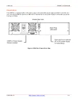
: If the LEDs on the front of the ION219 or the IONMM indicate one of the power supplies modules has
failed, remember that when looking at the rear of the chassis that the power supply on the left is PS1 / slot #22
and the power supply on the right is PS2 / slot # 23.
Looking at the front of the chassis, the LEDs are labeled PS1 and PS2. Looking in the IONMM module, the power
supply slots are labeled 22 and 23. Looking at the back of the chassis where the power supplies are, there is no
labeling to indicate which slot is 22 or PS1 or 23 or PS2.

