2: ManageLinx Overview
configuration and control. You can configure individual devices, set up automated device
discovery on remote networks, perform automated monitoring, and enable secure access
to any device visible to a participating Device Services Controller.
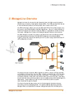
For an outside device to contact devices on private networks, there has to be a DSC on
the local segment of both devices and a DSM available to the DSCs. Alternatively, the
DSC can contact the DSM when an authorized local device requests communication with
another device using one of the DSC’s configured VIP (proxy) addresses.
The DSM acts as a publicly accessible call center server. It grants access for isolated
device communication through a secure encrypted tunnel by means of the DSC on the
local segment of the devices behind a firewall. It is also responsible for remote
management, maintenance, configuration and registration of detected DSCs and device
servers on the network.
The DSC’s primary responsibility is to provide a secure and encrypted communication
path for isolated public internet devices to communicate with devices local to the DSC
through firewalls on a local private network. The DSC periodically polls the configured
parent DSM to retrieve registry information such as discovered device data, maintenance
reports, and configuration information.
The DSM completely manages the DSCs. You create and maintain configuration profiles
on the DSM. You transfer configuration data from the DSM to the DSC with a USB flash
drive (provided). Then you use the web-based WebManager interface for access,
configuration, and management of the DSCs and VPN.
Configuration Sequence
The overall configuration sequence is as follows:
1. Install and configure the DSM. See Chapter 3: DSM Installation.
2. Via the Web Manager interface, connect to the DSM and define and configure all
elements of your ManageLinx network. See page 14.
3. Install and configure the DSCs. Use your PC and the Lantronix flash drive to copy a
bootstrap file from the DSM to each DSC. See Chapter 4: DSC Installation.
4. Configure specific communication routes. See Chapter 11: VIP Routes.
Product Information Label
The product information label on the underside of the unit contains the following
information about your specific unit:
Hardware address (also referred to as Ethernet or MAC address)
Bar code
Serial number
Product ID (name)
Product description
ManageLinx User Guide
9


