2: Description and Specifications
MatchPort b/g Pro Integration Guide
10
Note:
To minimize noises as well as voltage drops at the connection,
We recommend
direct connection of 3.3V and ground on the MatchPort b/g Pro to 3.3V power and ground
planes of the target board in place of heavy trace routing.
Reset
The MatchPort b/g Pro reset pin RESETIN# is an input-only pin and connects to an 811-
type reset IC. This input is for a pushbutton switch type manual reset. If no external reset
control is desired, leave this pin floating.
Minimum reset pulse is 2 ms.
There is an on board capacitor, 0.1uF to ground, at the RESETIN# to filter out transient
voltages. However, it is a good practice to have RESETIN# trace on the target board as
short as possible to avoid reset occurrences when transient voltages such as those
caused by ESD are present.
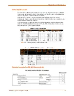
Ethernet Connections
The MatchPort b/g Pro provides Ethernet interface transmit ETX and receive data ERX
connections from a PHY device. Thus, before presenting signals to the outside world
using an RJ45 jack, a 1:1 Ethernet Magnetics is needed to interface and to isolate the
unit. A recommended connection diagram to an RJ45 jack with integrated 1:1 Ethernet
magnetics is shown below.
Figure 2-2. Connection Diagram to an RJ45 Jack
We recommend a low capacitance TVS diode array such as a Semtech SRV05-4 at
ETX+, ETX-, ERX+, ERX- if frequent transient voltages are present.
Summary of Contents for MatchPort b/g Pro
Page 1: ...Part Number 900 532 Revision B December 2011 MatchPort b g Pro Integration Guide...
Page 29: ...3 Demonstration Kit MatchPort b g Pro Integration Guide 29 Figure 3 3 Schematic...
Page 30: ...3 Demonstration Kit MatchPort b g Pro Integration Guide 30 Figure 3 3 Schematic continued...
Page 31: ...3 Demonstration Kit MatchPort b g Pro Integration Guide 31 Figure 3 3 Schematic continued...


