2: Description and Specifications
MatchPort b/g Pro Integration Guide
15
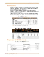
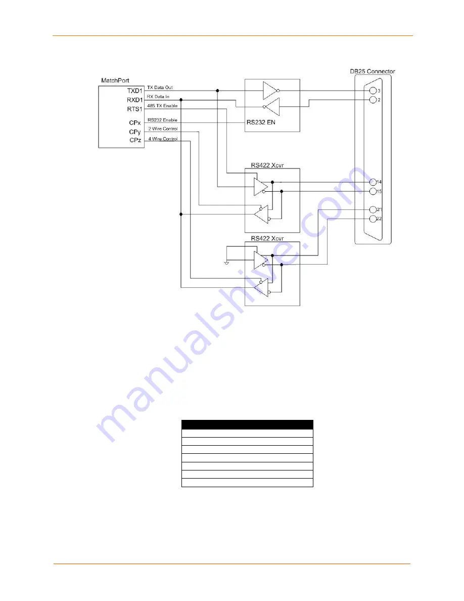
Figure 2-10. Separate RS422 Transceivers for 2-Wire and 4-Wire Setups
To protect the MatchPort b/g Pro and circuitry on the target board against ESD at serial
ports, the selected transceiver(s) should have RS232/422/485 bus-pin ESD protection
(typically around 15 KV) either on-chip or by external diode arrays.
IO Configurable Pins (CPs)
There are up to seven CPs if no DTR or DCD is used on the serial ports. All CPs have
internal pull-up resistors, but the value differs. See table.
CPs can be configured for special functions, like DTR, DCD, RS232/RS485 selection or
as general purpose Input or Output (pollable/controllable via CLI or Web Manager). For
more information see the User Guide.
PIN # NAME FUNCTION
P1.13
CP1
IO Configurable Pin 1
P1.15
CP2
IO Configurable Pin 2
P1.17
CP3
IO Configurable Pin 3
P1.19
CP4
IO Configurable Pin 4
P1.29
CP5
IO Configurable Pin 5
P1.31
CP6
IO Configurable Pin 6
P1.33
CP7
IO Configurable Pin 7
Summary of Contents for MatchPort b/g Pro
Page 1: ...Part Number 900 532 Revision B December 2011 MatchPort b g Pro Integration Guide...
Page 29: ...3 Demonstration Kit MatchPort b g Pro Integration Guide 29 Figure 3 3 Schematic...
Page 30: ...3 Demonstration Kit MatchPort b g Pro Integration Guide 30 Figure 3 3 Schematic continued...
Page 31: ...3 Demonstration Kit MatchPort b g Pro Integration Guide 31 Figure 3 3 Schematic continued...

