3: Demonstration Kit
MatchPort b/g Pro Integration Guide
26
JP7
pin/Signal
JP7
pin/Signal
Function
b/g Pro
13/CP5
14/DTRB
Jumper 13-14, CP5 drives DTR to RS232 transceiver.
15/CP6
16/DCDB
Jumper 15-16, CP6 receives DCD from RS232
transceiver.
Note:
CP allocation in the tables above is the most straightforward for this
specific board. However any CP can be assigned to any function. To reflect
actual CP use in the eventual product (in case different), jumpers can be
replaced with short wires to allow interchanging of connections.
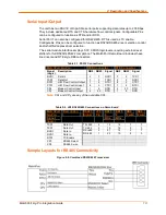
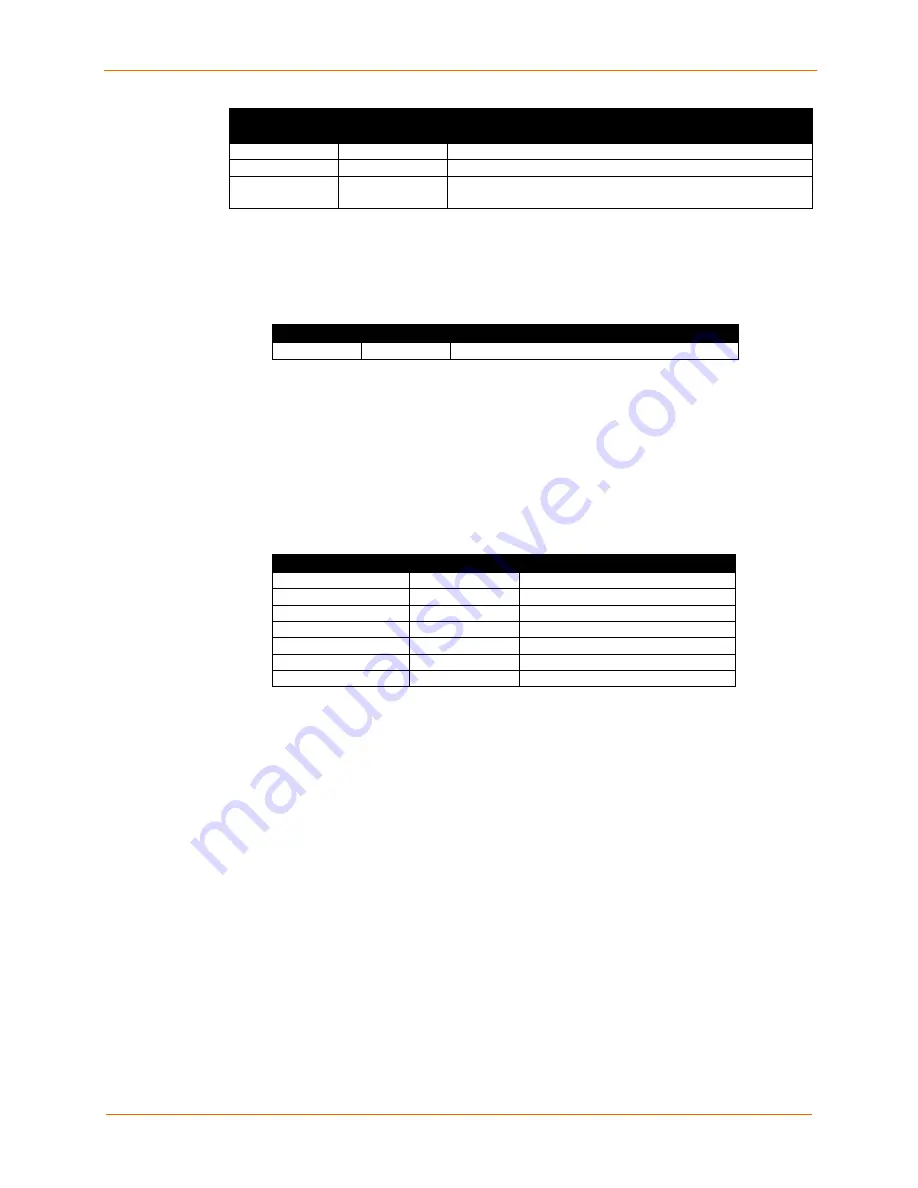
Table 3-7. Demo Board JP5 Jumper Configuration
Pin/Signal Pin/Signal Function
1/3V3
2/3V3_UUT
Jumper 1-2, MatchPort module power supply.
Note:
Jumper can be replaced with short wire to allow use of a current clamp or <50
milliohm resistor to allow use of voltmeter for current measurements.
If using CPs for any combination of the demo board configurations above, please use the
appropriate CP function selection as shown in Table 3-3 to Table 3-7.
If assigning a CP for any function other than the serial port, remove the jumper for the
associated CP pin from JP7 to avoid conflict with the serial port function.
Table 3-8
.
Demo Board Configurable Pin Jumper Configurations
Configurable Pin JP1 Function JP7,JP8 Function
CP1
LED12
JP7, CON1 DTR
CP2
LED11
JP7, CON1 DCD
CP3
LED10
JP7, CON1 RS485/232 Select
CP4
LED9
JP7, CON1 RS485 Duplex Select
CP5
LED8
JP8, CON2 DTR
CP6
LED7
JP8, CON2 DCD
CP7
LED6
JP8, leave open
Summary of Contents for MatchPort b/g Pro
Page 1: ...Part Number 900 532 Revision B December 2011 MatchPort b g Pro Integration Guide...
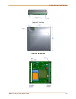
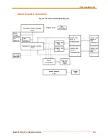
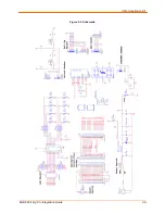
Page 29: ...3 Demonstration Kit MatchPort b g Pro Integration Guide 29 Figure 3 3 Schematic...
Page 30: ...3 Demonstration Kit MatchPort b g Pro Integration Guide 30 Figure 3 3 Schematic continued...
Page 31: ...3 Demonstration Kit MatchPort b g Pro Integration Guide 31 Figure 3 3 Schematic continued...


