3: Installation of the PremierWave XC HSPA+ Device
PremierWave® XC HSPA+ Intelligent Gateway User Guide
22
Hardware Components
Front/Top Panel
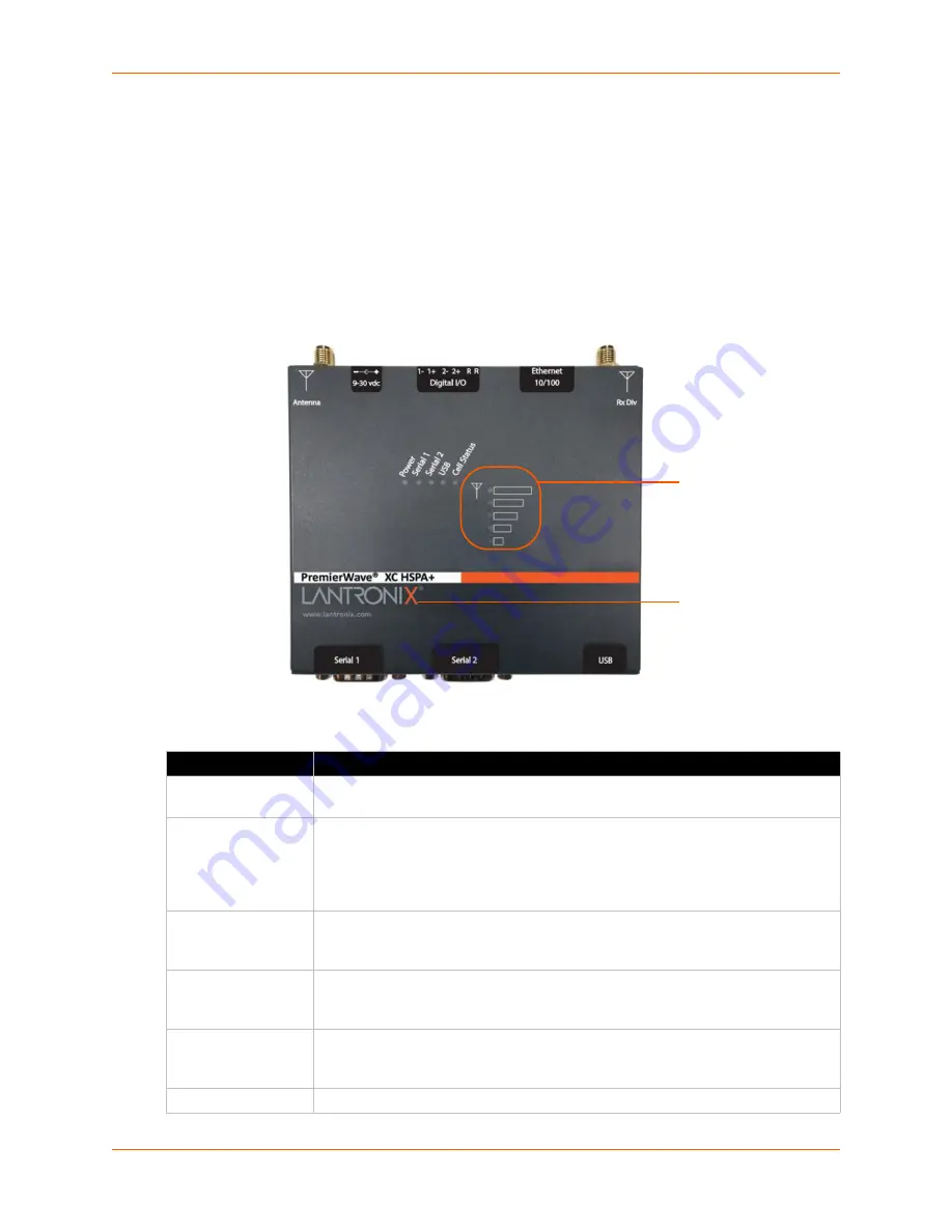
shows the top panel view of the PremierWave unit.
, and
list and explain the behavior of the LEDs on the top panel.
LED Indicators:
1 Power LED, 2 Serial Activity LEDs, 1 USB LED, 1 Cellular Status LED, 5 Signal
Strength LEDs (two of which are dual-colored), 1 Diagnostic LED, and 2 Ethernet LEDs (on the
RJ45 port).
Figure 3-1 PremierWave XC HSPA+ Unit
Table 3-2 PremierWave XC HSPA+ LEDs and Descriptions
LED
Description
Power
GREEN - displays a solid light when power is properly supplied
OFF - no power supplied
Cellular (Cell) Status
GREEN - displays solid when there is a connection to the packet domain on the
cellular network (e.g., a data or GPRS/UMTS/HSPA connection)
AMBER - displays solid when there is a connection to the cellular network (e.g., a
GSM connection)
OFF - indicates WWAN (cellular) interface is inactive or disabled
Serial 1
GREEN - flashes when Serial port 2 is transmitting data
AMBER - flashes when Serial port 2 is receiving data
OFF - when no data is being transmitted or received through Serial port 2
Serial 2
GREEN - flashes when Serial port 2 is transmitting data
AMBER - flashes when Serial port 2 is receiving data
OFF - when no data is being transmitted or received through Serial port 2
USB
GREEN - displays a solid light when a USB device is connected to and is
functioning properly
OFF- when no USB device is connected
Signal Strength
Indicates cellular signal strength when connection is established (see
Signal
Strength
LEDs
Diagnostic
LED


