Lantronix
SISPM1040-582-LRT CLI Reference
33757 Rev. J
Page
246
of
272
27 MRP Pre-Requisites and Application Examples
You can configure
Media Redundancy Protocol (MRP) parameters via the Web UI at Configuration > MRP and
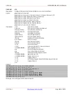
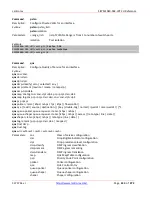
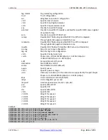
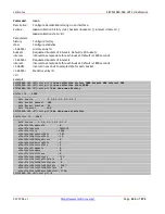
monitor them at Monitor > MRP, and via the CLI. See the
CLI Reference
for Command Line operation.
According to ANSI,
is applicable to high-availability automation networks based on
IEEE 802.3 Ethernet technology
. It specifies a recovery protocol based on a ring topology,
designed to react deterministically on a single failure of an inter-switch link or switch in the network, under the
control of a dedicated Media Redundancy Manager (MRM) node.
Media Redundancy Protocol per IEC 62439-2 is an interoperable ring technology designed to allow a switch to
connect onto a universal redundant high speed ring. MRP is self-healing and self-adjusting, requiring no operator
interaction. MRP is based on the concept of standby connections for seamless redundancy.
27.1 MRP Description
1.
MRP operates at the MAC Layer of the Ethernet Switch.
2.
The Ring Manager is called the Media Redundancy Manager (MRM).
3.
Ring Clients are called Media Redundancy Clients (MRCs).
4.
MRM and MRC ports support three Status Types:
a.
Disabled
ring ports drop all the received frames.
b.
Blocked
ring ports drop all the received frames except the MRP control frames.
c.
Forwarding
ring ports forward all the received frames.
5.
Ring Reconfiguration speed is 200 ms for 50 switches on average.
6.
The MRM continuously sends Watchdog Packets into the ring network to verify communication between ring
points.
7.
During normal operation, no packets are transmitted over the redundant link.
8.
When the MRM no longer receives the Watchdog Packets it sent out, the redundant path is immediately
activated, and it becomes the primary layer 2 packet path.
9.
When the failed link is restored:
a.
The MRM switches back to normal operation and the first Path becomes the primary path again.
b.
You can configure a period of time before the MRM switches back to the primary path (to prevent the
circuit from flapping if it is not stable).
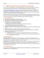
27.2 MRP Operation
Normal operation
: the network works in the
Ring-Closed
status. In this status, one of the MRM ring ports is
blocked, while the other is forwarding. Conversely, both ring ports of all MRCs are forwarding. Loops are avoided
because the physical ring topology is reduced to a logical stub topology.
Failure mode
: the network works in the
Ring-Open
status. For instance, in case of failure of a link connecting two
MRCs, both ring ports of the MRM are forwarding. The MRCs adjacent to the failure have a blocked and a
forwarding ring port; the other MRCs have both ring ports forwarding. The physical ring topology is also a logical
stub topology in the Ring-Open status.
27.3 Related Devices
MRP is supported on SISPM1040-582-LRT, SISPM1040-362-LRT, SISPM1040-384-LRT-C and SISGM1040-284-LRT,
SISPM1040-3166-L, and SISPM1040-3248-L.

