background image

Lantronix 


SISPM1040-582-LRT Install Guide


33755 Rev. H 

https://www.lantronix.com/


Page 

46

  of 

51


Recording Device and System Information 

After performing the troubleshooting procedures, and before calling or emailing Technical Support, please record 

as much information as possible to help the Tech Support Specialist. 

1.


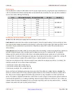
Select the Configuration > System > Information menu path. From the CLI, use the show commands to gather 

the information below or as requested by the Tech Support Specialist.   

2.


Model Name: _______________________________ PCB Rev (e.g., A1 or Rev A2): ___________________________________   

Hardware Version: __________________________  Mechanical Version: ____________________________________________ 

Firmware Version: ___________________________ System Date: ___________________________________________________ 

3.


LED Status: ____________________________________________________________________________________________________ 

________________________________________________________________________________________________________________ 

4.


Provide additional information to your Tech Support Specialist. See the “Troubleshooting” section above.   

Your Lantronix service contract number: _______________________________________________________________ 

Describe the failure: ________________________________________________________________________________________________ 

______________________________________________________________________________________________________________________ 

______________________________________________________________________________________________________________________ 
A description of any action(s) already taken to resolve the problem (e.g., changing mode, rebooting, etc.): 

______________________________________________________________________________________________________________________ 

______________________________________________________________________________________________________________________ 

______________________________________________________________________________________________________________________ 
The model #, serial # and rev of all involved Lantronix products in the network: ________________________ 

_______________________________________________________________________________________________________________________ 

_______________________________________________________________________________________________________________________ 
A description of your network environment (PDs, cable type, etc.): ________________________________________________ 

_______________________________________________________________________________________________________________________ 

_______________________________________________________________________________________________________________________ 
The device history (i.e., have you returned the device before, is this a recurring problem, etc.): _____________________ 

_______________________________________________________________________________________________________________________ 

________________________________________________________________________________________________________________________ 
Any previous Return Material Authorization (RMA) numbers: ________________________________________________________ 

Attach any screen captures, config files, diagnostic results, server reports, etc. ______________________________________ 
_________________________________________________________________________________________________________________________ 


Summary of Contents for SISPM1040-582-LRT

Page 1: ...SISPM1040 582 LRT Managed Hardened PoE Switch 8 10 100 1000Base T PoE Ports 2 100 1000Base X SFP Slot Install Guide Part Number 33755 Revision H September 2022 ...

Page 2: ...nformation in this publication Lantronix does not make and specifically disclaims all warranties of any kind express implied or otherwise regarding title non infringement fitness quality accuracy completeness usefulness suitability or performance of the information provided herein Lantronix shall have no liability whatsoever to any user for any damages losses and causes of action whether in contra...

Page 3: ...even death WARNING Equipment grounding is vital to ensure safe operation The installer must ensure that the power module is properly grounded during and after installation Failure to observe this warning could result in an electric shock even death WARNING A readily accessible suitable National Electrical Code NEC or local electrical code approved disconnect device and branch circuit protector mus...

Page 4: ...e Switch on a Wall Optional 22 Grounding Screw 23 Installing SFP Modules 24 Connecting Devices 24 Connecting Powered Devices PDs 25 Connecting the DI DO Digital Input Digital Output Relay 25 Connecting P1 and P2 54 VDC Power Inputs 27 Power Supply Specifications 28 4 Initial Switch Configuration 34 Connect the Switch to a Windows 10 PC 34 Initial Switch Configuration via Web Browser 34 Initial Swi...

Page 5: ...gy Efficient Ethernet EEE for green Ethernet application IPv4 IPv6 L3 static route IEC 62439 2 MRP Media Redundancy Protocol IPv4 IPv6 dual protocols Supports Jumbo Frame up to 9K bytes Benefits Feature rich Specifications to support various applications The switch delivers extensive industrial and carrier grade functionalities including R Ring ITU T G 8031 ITU T G 8032 IEEE 1588v2 PTP OAM CFM etc...

Page 6: ...2V 57 VDC Optional Accessories sold separately ConsoleFlow Centralized Management Software for PoE Switches Remote Environment Management REM and IoT Gateway products Sold separately LPM Lantronix Provisioning Manager Lantronix Provisioning Manager LPM allows easy administration of Lantronix devices LPM lets you quickly update firmware update configuration and provision one or more devices simulta...

Page 7: ... Dimensions Weight Mounting Dimensions WxHxD Weight Mounting Type Millimeters Inches Kilograms Pounds 62 x 135 x 130 2 4 x 5 3 x 5 1 0 8 1 7 DIN rail Wall Optional Voltage and Frequency Primary Power Supply DC Input Voltage DC Nominal 54 VDC dual inputs DC Operating Range 48 to 57 VDC IEE 802 3af 48 57VDC 802 3at 52 57VDC 802 3bt 54 57VDC Power Consumption 13W without PoE PoE Support The switch ca...

Page 8: ...e EMS EN61000 4 2 ESD EN61000 4 3 RS EN61000 4 4 EFT EN61000 4 5 for RJ45 Port Surge 6KV EN61000 4 6 CS EN61000 4 8 PFMF EMI FCC Part 15 Class A Safety CE EN62368 1 IEC62368 1 Plenum UL Certified UL 2043 and UL 2108 Certified Transportation NEMA TS2 traffic signaling equipment Mechanical Stability Vibration IEC 60068 2 6 Shock IEC 60068 2 27 Freefall IEC 60068 2 32 Compliant Substation IEC 61850 3...

Page 9: ... Monitoring Display visual chart of network traffic of all devices and monitor every port at any time from switches Troubleshooting Network diagnostic between master switch and devices Support protection mechanism such as rate limiting to protect your devices from brute force downloading Support performance management and link management through IEEE 802 3ah and IEEE 802 1ag Y 1731 Google Map API ...

Page 10: ...and accounting MD5 hash guest VLAN single multiple host mode and single multiple sessions Supports IGMP RADIUS based 802 1X Dynamic VLAN assignment Layer 2 Isolation Private VLAN Edge PVE aka protected ports provides L2 isolation between clients in the same VLAN Supports multiple uplinks Port Security Locks MAC addresses to ports and limits the number of learned MAC address IP Source Guard Prevent...

Page 11: ...rum was formed to standardize discovery and control of networked devices See the Open Connectivity Foundation webpage s Flow The industry standard for monitoring high speed switched networks It gives complete visibility into the use of networks enabling performance optimization accounting billing for usage and defense against security threats IEEE 802 1ab LLDP Used by network devices for advertisi...

Page 12: ... delay time when PoE switch boots up to protect switch from misuse of the PDs When rebooting the PoE port will start to provide power to the PD after a configurable delay time ConsoleFlow and LPM ConsoleFlow Auto discovery of devices connected to the switch interfaces Perform on demand backup and restore of device configuration Perform secure remote device firmware upgrades Lantronix hosted public...

Page 13: ... defaults and troubleshoot the switch Related Manuals SISPM1040 582 LRT Quick Start Guide 33754 SISPM1040 582 LRT Install Guide 33755 this manual SISPM1040 582 LRT Web User Guide 33756 SISPM1040 582 LRT CLI Reference 33757 SISGM1040 284 LRT API User Guide 33827 Release Notes version specific For Lantronix Drivers Firmware etc go to the Product Support webpage logon required For Lantronix Manuals B...

Page 14: ...itch including descriptions of Front and Back Panels LEDs RESET button DIP Switch Grounding Screw D1 Digital Input Digital Output relay P1 and P2 DC Power Inputs Back Panel The SISPM1040 582 LRT back panel provides for mounting the switch on a wall or in a 19 inch rack See Mounting the Switch on a DIN Rail on page 21 or Mounting the Switch on a Wall Optional on page 22 ...

Page 15: ...de 33755 Rev H https www lantronix com Page 15 of 51 Front Panel The SISPM1040 582 LRT front panel ports LEDs Power Input terminal block DI DO terminal block CONSOLE port DIP Switch RESET button and Ground screw are shown and described below ...

Page 16: ...tatus of each port Users can check these LEDs to understand the port status The following tables detail the various LED functions Table 1 Power LEDs LED Color State Description P1 Power 1 Green On The switch is powered ON correctly Off The switch is not receiving power from power 1 P2 Power 2 Green On The switch is powered ON correctly Off The switch is not receiving power from power 2 Table 2 Sys...

Page 17: ...een disabled through the switch user interface RJ45 Ports Down Green On The port is enabled and supplying power to connected device Amber On An abnormal state such as overload status has been detected in the switch Off The port has no active network cable connected or it is not connected a PoE PD device Otherwise the port may have been disabled through the switch user interface SFP Ports Green On ...

Page 18: ... traffic in a ring topology while also ensuring that the Ethernet layer remains loop free The two position DIP switch is labeled RC 1 Rapid Chain and RM 2 Ring Master The DIP switch lets you manually set DIP switch settings and not have to access the Web UI or the CLI to configure a ring The table below shows DIP switch settings for Ring Master and Rapid Chain setup via the DIP switch Table 5 Ring...

Page 19: ...Factory Defaults to restore the original factory default settings back to the switch Note Use the table below to determine which task is being performed by reading LED status while pressing the RESET button Once the LED behaviors are correctly displayed just release the RESET button Table 6 RESET Button Operation Task Press RESET button for SYS LED Behavior Port Status LED Behavior Reset the Switc...

Page 20: ...IP cameras or outdoor Wi Fi APs then you are strongly suggested to install a surge protector or surge suppressor to protect the switch Compliant with 802 3at in Environment A when using an isolated power supply For 802 3at Environment B applications i e building to building copper to copper endpoint connections 1 use an Ethernet network isolator module PoE disabled or 2 use mid span injector s e g...

Page 21: ...ttach the DIN Rail mounting kit to the rear panel of the chassis Insert screws and tighten then with a screwdriver to secure the kit 2 Insert the upper lip of the DIN rail into the DIN rail mounting kit and press the switch towards the DIN rail until it snaps into place 3 Make sure that the switch is attached securely to DIN Rail ...

Page 22: ...ing the Switch on a Wall Optional 1 Attach the wall mounting plates to rear panel of the chassis Insert screws and tighten them with a screwdriver to secure the plates 2 Install user supplied screws on the appropriate location on the wall 3 Make sure that the switch is attached securely to the wall ...

Page 23: ...te paths or conduits to route wiring for power and device data cables To avoid interference wires with different signal characteristics route separately If power wiring and device data cables must cross make sure that the wires are perpendicular at the intersection point Use the type of signal transmitted through a wire to determine which wires should be kept separate The rule of thumb is wiring t...

Page 24: ... off the switch Note The SFP ports should use UL Listed Optional Transceiver product Rated 3 3Vdc Laser Class 1 See the SFP manual for important information See the Fiber Optic Association for fiber optics standards and certification 1 Note the proper orientation and insert the module into the SFP port 2 Press firmly to ensure that the module seats into the connector Connecting Devices All CONSOLE...

Page 25: ...he maximum power with maximum cable loss Connecting the DI DO Digital Input Digital Output Relay 1 Insert the negative ground positive DI DO Relay wires into the and terminals respectively 2 To keep the DI DO Relay wires from pulling loose use a small flat blade screwdriver to tighten the wire clamp screws on the front of the Terminal Block connector 3 Insert the Terminal Block connector prongs in...

Page 26: ... time DO will automatically switch to abnormal and send a signal to connected devices switch will have system recorded For example a water level application Setting low water level DI normal High water level DI abnormal DIO connected to external alarm notification DI will show normal when the water level is low DI will not send signal to DO DI will show abnormal when sensor senses high water level...

Page 27: ...e shipped set to 48VDC If you unbox the PS plug it into the SISPM1040 582 LRT and then connect 60W cameras to the switch the cameras will not power up by POE The SISPM1040 582 LRT needs 52 57VDC to power all 8 ports You must use a small Phillips screwdriver to turn up the PS potentiometer to get the VDC up to 52 57VDC Note Meanwell 25160 power supplies shipped after Sept 2019 have the default sett...

Page 28: ...ting temp 25 70 C Description AC DC Industrial DIN rail power supply Output 48Vdc at 10A Metal casing Ultra slim width 85 5mm Net weight grams 1820 Format DIN rail Application Installation UL 508 ITE EN UL IEC 60950 Output Power W 480 Output Voltage V 48 Output Current A 10 Input Voltage V 90 264V Universal Input 110 230V IP Rating No IP Format DIN rail Control Signals DC OK Dimming Technology No ...

Page 29: ...Lantronix SISPM1040 582 LRT Install Guide 33755 Rev H https www lantronix com Page 29 of 51 Power Supply Views 25160 Front Back Top Bottom ...

Page 30: ...M1040 582 LRT Install Guide 33755 Rev H https www lantronix com Page 30 of 51 Power Supply Dimensions 25160 Width 85 5 mm 3 36 in Height 125 2 mm 4 92 in Depth 128 5 mm 5 05 in ADMISSIBLE DIN RAIL TS35 7 5 OR TS35 15 ...

Page 31: ...ptions 25160 Terminal Pin No Assignment TB1 Pin No Assignment 1 FG 2 AC N 3 AC L Terminal Pin No Assignment TB2 Pin No Assignment 1 2 DC OUTPUT V 3 4 DC OUTPUT V 5 6 Relay Contact 7 8 NC DC OK Relay Contact Contact Close PSU turns on DC OK Contact Open PSU turns off DC Fail Contact Ratings max 30V 1A resistive load ...

Page 32: ... 55VDC Voltage Tolerance 1 0 Line Regulation 0 5 Load Regulation 1 0 Setup Rise Time 300ms 60ms Hold Up Time 20ms Power Input Voltage Range Switch Selectable 88 132VAC 124 370VDC Frequency Range 47 63Hz Efficiency 94 AC Current Typical 2 6A 115VAC 1 3A 230VAC Inrush Current Cold 33A 115VAC 65A 230VAC Protection Overload 105 160 Overvoltage 56 65V Dimensions Width 2 48 63 mm Depth 5 26 113 5 mm Hei...

Page 33: ...o Fan tachometer monitoring for low speed or lock conditions o Over or under temperature o 12 24V output out of spec Output 1 Voltage 56V terminal block Regulation 2 Current Rating 5 7A Power Rating 315W Output 2 Voltage 24V terminal block 5624T 12V terminal block 5612T Regulation 5 Current Rating 1 25A Power Rating 30W Input Voltage Range 100 240VAC Input Frequency Range 47 63 HZ Power Consumptio...

Page 34: ...Pv4 7 Click on the Properties tab 8 Click the Use the following IP address button 9 Give the same IP subnet as the switch 192 168 1 5 your switch 77 Subnet mask 255 255 255 0 10 Click OK 11 Connect your network cable from your PC to your switch 12 In your web browser address bar type the IP for the switch 192 168 1 77 and hit Enter 13 Enter the default User name admin and Password admin all lower ...

Page 35: ...ool for every Ethernet network installation 7 Improper Network Topologies Make sure you have a valid network topology If you no longer experience the problems the new topology is probably at fault Also make sure your network topology contains no data path loops 8 Check the port configuration A port on your Switch may not be operating as you expect because it has been put into a blocking state by S...

Page 36: ...port is not connected or the connection is not working 1 Check if the cable connector plug is firmly inserted and locked into the port at both the switch and the connected device 2 Make sure the connected device is up and running correctly 3 If the symptom still exists try a different cable or different port in order to identify if it is related to the cable or specific port 4 Check if the port is...

Page 37: ...l for IP surveillance cameras that require more throughput or a various other equipment such as LCD displays computer workstations and biomedical equipment Min cable type Cat5e recommend Cat 6A cabling PoE Standards Comparison PoE Type 1 PoE Type 2 802 3bt Type 3 802 3bt Type 4 Property 802 3af PoE Type 1 802 3at PoE Type 2 802 3bt Type 3 802 3bt Type 4 Power Available at PD 12 95 W 25 50 W 51 W 7...

Page 38: ... power for each device PoE Type 2 can support devices such as more complex surveillance cameras that pan tilt or zoom as well as wireless access points with six antennas LCD displays biometric sensors and tablets Type 3 Also known as 4 pair PoE 4P PoE PoE UPOE Related standard IEEE 802 3bt Maximum power to port 60W PoE Type 3 uses all four pairs in a copper cable Currently in development with IEEE...

Page 39: ...E and data as well as between every port in a multi port PSE This isolation between ports requirement de facto determines a completely separate power supply per port which makes multi port PSE s for outdoor PD deployment impractical Environment B is therefore an indoor PSE outdoor PD a k a indoor outdoor or outdoor PSE outdoor PD a k a outdoor outdoor environment This means only single port PSE s ...

Page 40: ...nly Mode B Typical PD Power Requirements 1 8 Watts Lantronix M GE ISW SFP 01 PD Class 1 Powered Device 0 44 Watts 3 84 Watts 13W IP Camera VoIP Phone Wireless Access Point Networked Audio 30W IP Telephone WiMAX Access Point PTZ Camera Remote Computer Terminal 60W Door Access System Video Phone Thin Client 100W Digital Signage Display Point of Sale System LCD TV Computer Monitor 200W Larger TV Larg...

Page 41: ... capacitance as the detection signature that does not completely comply with the 802 3af specs By enabling this option the switch will probe for legacy PDs and if a legacy PD is detected the switch will provide power to the PD PoE Connectivity Arcing and Temperature Issues PoE is not live until powered device PD and powered sourcing equipment PSE handshake When unplugging live PoE an arc or spark ...

Page 42: ...tured wiring plan resulting in greater power being available to end devices and adds a mechanism to better manage the available power budget 1 4 491a Type 3 PD A single signature PD that requests Class 1 to Class 6 or a dual signature PD that requests Class 1 to Class 4 on both Modes during Physical Layer classification Additionally the PD implements Multiple Event classification and accepts power...

Page 43: ...ss 0 to Class 3 power levels and provides power over 2 pairs Type 2 PD A PD that requests Class 4 during Physical Layer classification supports 2 Event Classification and supports Data Link Layer classification Type 2 PSE A PSE that supports Class 0 to Class 4 power levels and provides power over 2 pairs Type 3 PD A single signature PD that requests Class 1 to Class 6 or a dual signature PD that r...

Page 44: ...t negated during installation of a new network or during modification of an existing network Patch Panel Considerations It is possible that the current carrying capability of a cabling cross connect may be exceeded by a PSE The designer should consult the manufacturer s specifications to verify compliance with the appropriate requirements Electromagnetic Emissions The PD and PSE powered cabling li...

Page 45: ...Lantronix SISPM1040 582 LRT Install Guide 33755 Rev H https www lantronix com Page 45 of 51 Product Labeling Box Labels Device Label ...

Page 46: ...s already taken to resolve the problem e g changing mode rebooting etc ______________________________________________________________________________________________________________________ ______________________________________________________________________________________________________________________ ___________________________________________________________________________________________...

Page 47: ...io interference regulations of the Canadian Department of Communications Le présent appareil numérique n émet pas de bruits radioélectriques dépassant les limites applicables aux appareils numériques de la Class A prescrites dans le Règlement sur le brouillage radioélectrique édicté par le ministère des Communications du Canada Declaration of Conformity DoC Manufacture s Name Lantronics Inc Manufa...

Page 48: ...s dans un enceinte uniquement accessible à l aide d un outil adapté à environnement Cet équipement peut être utilisé dans la classe I division 2 groupes A B C et D ou des emplacements non dangereux seulement AVERTISSEMENT RISQUE D EXPLOSION NE PAS SE DÉCONNECTER LORSQUE LE CIRCUIT EST VIVANT OU À MOINS QUE LA ZONE NE SOIT LIBRE DE CONCENTRATIONS IGNIFIABLES High Risk Activities Disclaimer Componen...

Page 49: ...NING The power module has a provision for grounding Equipment grounding is vital to ensure safe operation The installer must ensure that the power module is properly grounded during and after installation Failure to observe this warning could result in an electric shock even death WARNING A readily accessible suitable National Electrical Code NEC or local electrical code approved disconnect device...

Page 50: ...ften worden geïnstalleerd Sécurité électrique IMPORTANT Cet équipement doit être utilisé conformément aux instructions de sécurité Sähköturvallisuus TÄRKEÄÄ Tämä laite on asennettava turvaohjeiden mukaisesti Sicurezza elettrica IMPORTANTE questa apparecchiatura deve essere installata rispettando le norme di sicurezza Elektrisk sikkerhet VIKTIG Dette utstyret skal installeres i samsvar med sikkerhe...

Page 51: ...ry Suite 250 Irvine CA 92618 USA Toll Free 800 526 8766 Phone 949 453 3990 Fax 949 453 3995 Technical Support Tel 1 800 526 8766 Tel 1 949 453 3990 or https www lantronix com technical support Sales Offices For a current list of our domestic and international sales offices go to the Lantronix web site at www lantronix com about contact ...

Reviews: