Lantronix
SISPM1040-xxxx-L3 Install Guide
33855 Rev. A
21
Digital Input and Digital Output Use Case
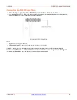
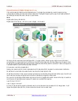
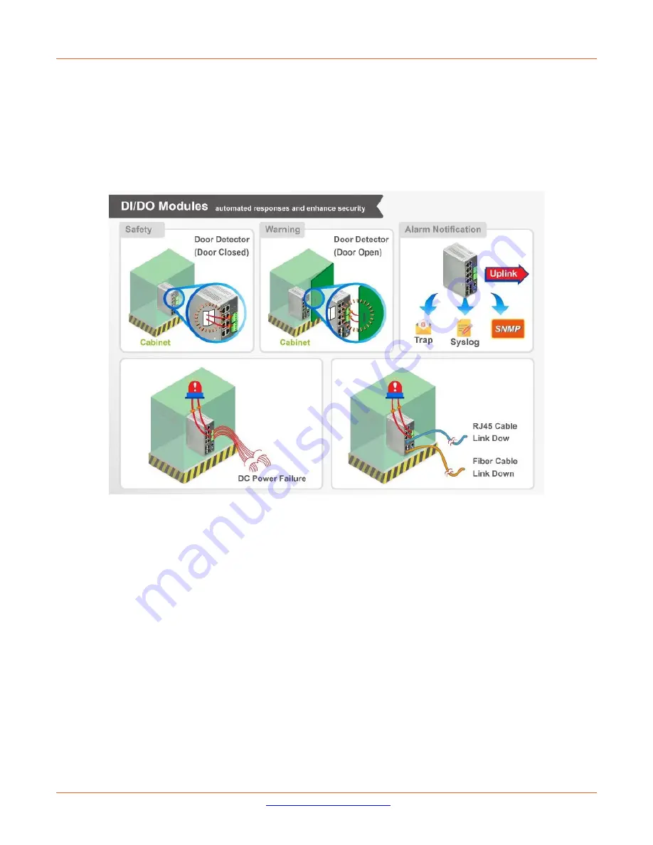
The switch supports Digital Input and Digital Output. The Digital Input enables the switch to detect and log
external device status (such as door intrusion detector). The Digital Output could be used to tell administrators if
the switch port shows link down, link up or power failure.
Note
:
Digital output (relay): 24VDC/1A
Digital input: level 0(Low) -> 0V to 6V, level 1 (High) -> 10V to 24V
DI: Use to receive external signal and trigger DO. You may set the voltage input as high or low as DI normal;
when DI stays in normal (assume it’s set as low), then DO will not response. But the voltage input change to high,
DI will show high/ abnormal and at the same time, DO will automatically switch to “abnormal” and send a signal to
connected devices, switch will have system recorded.
For example, a water level application:
Setting: low water level: DI normal. High water level: DI abnormal, DIO connected to external alarm notification.
DI will show “normal” when the water level is low. DI will not send signal to DO.
DI will show “abnormal” when sensor senses high water level and will send signal to DO at the same time. DO will
turn to abnormal and send signal to external alarm notification to trigger the alarm LED.
DI is used for connecting external alarm devices and once it is triggered the switch can send the trap. An external
alarm device (for example: power supply, IP camera) can activate this input pin.
Level 0 (Low): 0V to 6V
Level 1 (High): 10V to 24V
For DO, it’s similar but the switch is the alarm device, when the switch has temperature or voltage alarm, it will
trigger the digital output (24V/1A) to the external device such as a contact relay.

