background image


SISTP1040-551-LRT   

Unmanaged Hardened Gigabit Ethernet PoE++ Switch


Install Guide 


Part Number 33841 

Revision A January 2022 


Summary of Contents for SISTP1040-551-LRT

Page 1: ...SISTP1040 551 LRT Unmanaged Hardened Gigabit Ethernet PoE Switch Install Guide Part Number 33841 Revision A January 2022 ...

Page 2: ... or 1 800 260 1312 Email techsupport transition com Sales Offices For a current list of our domestic and international sales offices go to the Lantronix web site at www lantronix com about contact Disclaimer All information contained herein is provided AS IS Lantronix undertakes no obligation to update the information in this publication Lantronix does not make and specifically disclaims all warra...

Page 3: ...tures Set via DIP Switch 13 1 Power Alarm 13 2 Broadcast Storm Rate Limit 13 3 Jumbo Frame Support 13 4 PoE PoH PoE 802 3bt Mode 14 5 Enable PoE power cutoff when no SFP link PSE Link Pass Thru 14 Alarm Relay Connection 15 Power Connection 16 3 Power Supply Information 17 25160 Hardened DIN Rail Mounted Power Supply 17 25160 Features 17 25160 Specifications 17 25160 Dimensions and Terminal Pin Ass...

Page 4: ...cluded Industrial power supply sold separately Optional Accessories Order Separately 25160 Hardened DIN Rail Mounted Power Supply Input 90 264 VAC 127 370 VDC Output 48 55 VDC 10A 480 Watts PS DC DUAL 5624T Stand Alone Industrial Power Supply 345 Watt Isolated Power Supply with 56VDC and 12 24VDC Dual Output SFP Modules Lantronix offers a broad range of SFPs OCA P181610 18x16x10 Polycarbonate Encl...

Page 5: ... Jumbo Frame support On Off SW4 PoE On PoH Mode Off 802 3bt Mode SW5 LPT PSE LPT On Off Storm Control Multicast Broadcast Flooding Storm Control per system basis enable disable Flow Control IEEE 802 3x Full Duplex Flow control is disabled by default the switch will enable auto negotiation when the link partner has flow control enabled QoS QoS IEEE 802 1p 4 queues per port Supports Strict priority ...

Page 6: ...P1040 551 LRT Install Guide 33841 Rev A 6 Application Example The switch is ideal for applications such as PoE Lighting IP camera with heater digital signage and situations involving PDs that require higher power PoE ...

Page 7: ... The information supplements the text or highlights important points Safety Instructions When a connector is removed during installation testing or servicing or when an energized fiber is broken a risk of ocular exposure to optical energy that may be potentially hazardous occurs depending on the laser output power The primary hazards of exposure to laser radiation from an optical fiber system are ...

Page 8: ...Lantronix SISTP1040 551 LRT Install Guide 33841 Rev A 8 Dimensions ...

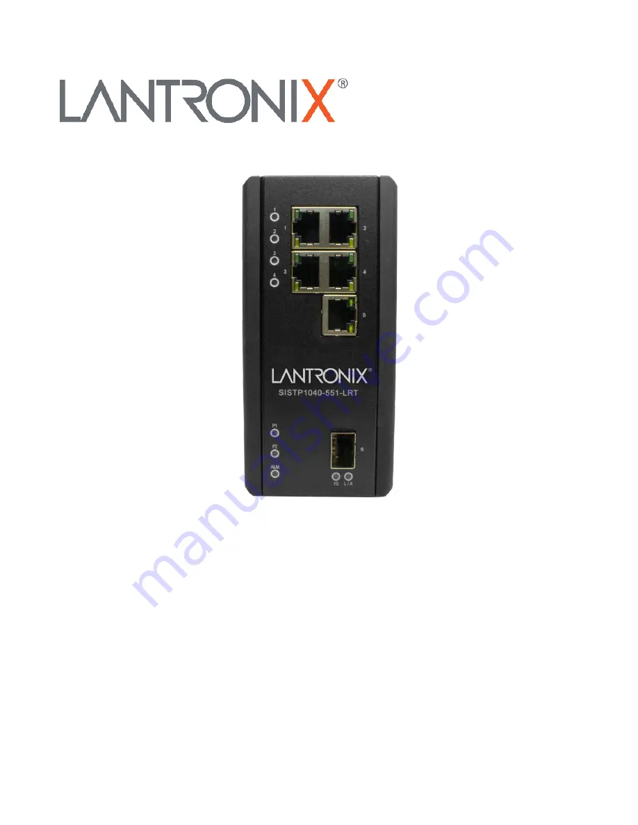
Page 9: ...nels The front panel provides the LEDs and Ethernet interface connections RJ45 Fiber SFP The top panel contains the Power and Alarm connections Ground screw and DIP switch The back panel contains holes for DIN Rail and Wall Mounting Front Panel Top Panel 1 Back Panel Top Panel 2 ...

Page 10: ...cket and screws 2 Hook the unit over the DIN rail 3 Push the bottom of the unit towards the DIN Rail until it snaps into place Wall Mounting 1 Mark and prep holes in the wall surface for mounting 2 Screw the wall mount plate onto the switch with the M4 screws provided 3 Screw the switch and wall mount plate onto the wall screws not provided ...

Page 11: ...ect the Ethernet interface via RJ45 1 Connect to a PC using a straight through or a crossover Ethernet cable 2 Connect the switch to an Ethernet device using UTP Unshielded Twisted Pair or STP Shielded Twisted Pair Ethernet cables The pin assignment of RJ 45 connector is shown in the table and figure below Pin Assignment 802 3af at Assignment 802 3bt Assignment 1 2 T Rx T Rx Negative VPort Negativ...

Page 12: ...ts to the transmit TX port of the other device when making your fiber optic connections Note see the related SFP device manual for important Safety warnings See the Lantronix SFP page for our full line of SFP transceivers See the FOA webpage for additional information The Fiber Optic Association Inc is an international non profit educational association chartered to promote professionalism in fibe...

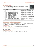
Page 13: ...ect PoE PoH Mode Set the DIP switch to ON before powering up the switch Off Select PoE 802 3bt Mode 5 On Enable PoE Power Cutoff when no SFP link PSE LPT Link Pass Thru On Off The feature becomes active immediately after setting the DIP switch to ON Off Disable PoE Power Cutoff Descriptions of Features Set via DIP Switch The top panel DIP switch is used to enable disable Power alarm broadcast stor...

Page 14: ... 90 W 71W 90 W Cat5e 6 100 m 2 4 pairs PoH PoH 95 W 72 W 95 W Cat5e 6 100 m 4 pairs Extended power capability allows PD to reach upper power limit if cable length and cable resistance is known 5 Enable PoE power cutoff when no SFP link PSE Link Pass Thru DIP switch 5 controls PoE power cutoff when there is no SFP link This feature is like a media converter s Link fail Pass Through LPT feature On E...

Page 15: ...hown right and below By inserting the wires and setting the DIP switch of the respective Port Alarm to ON the relay output alarm will detect any port failures and form a short circuit The alarm relay is Normal Open and it will be Closed when any power failure is detected The alarm relay output contacts have a current carrying capacity of 24VDC 1Amp via the 2 pin ALM terminal block ...

Page 16: ...ock into the switch top panel receptacle 2 Insert the positive and negative wires AWG 14 26 into the PWR and PWR contacts on the terminal block and tighten the wire clamp screws to prevent the wires from being loosened 3 Caution DC power must be connected to an isolated power supply See chapter 3 Power Supply Information on page 17 below 4 Verify proper LED status see chapter 4 Troubleshooting LED...

Page 17: ...ency Range 47 63Hz Efficiency 94 AC Current Typical 5A 115VAC 2 5A 230VAC Inrush Current Cold 40A 115VAC 80A 230VAC Protection Overload 110 160 Overvoltage 57 6 64 8V Dimensions Width 3 37 85 5 mm x Depth 5 06 128 5 mm x Height 5 99 152 2 mm Environment Operating Temp 25 C to 70 C Storage 40 C to 85 C Humidity 20 to 90 non condensing Weight 3 53 lbs 1 6 kg MTBF 112 9 Khrs Safety standards UL508 TU...

Page 18: ...Lantronix SISTP1040 551 LRT Install Guide 33841 Rev A 18 25160 Dimensions and Terminal Pin Assignments 25160 Views Front Top Back ...

Page 19: ... Supply Stand Alone Hardened Power Supply 345 Watt Isolated Power Supply with 56VDC and 12 24VDC Dual Output See the PS DC DUAL 5624T Power Supply Install Guide for more information See the PS DC DUAL 5624T product page at https transition com products accessory ps dc dual series ...

Page 20: ...ic detected Off Ethernet link down 1G Copper port Speed On Yellow A 1000Mbps connection is detected Off No link a 10Mbps or 100 Mbps connection is detected L A SFP port Link Act On Green Ethernet link up Flashing Green Ethernet link up and there is traffic detected Off Ethernet link down 1G SFP port Speed On Yellow SFP port speed 1000 Mbps connection is detected Off No link or a SFP port speed 100...

Page 21: ...or loose power connections power losses or surges at the power outlet See the related section of this manual for details 2 Check the port LEDs If the Link Act LED is not lit then verify that the copper and fiber cable requirements are met See Technical Specifications on page 5 3 Make sure that the function you are trying to use is supported See Features on page 4 4 Verify the install procedures we...

Page 22: ...s This equipment has been tested and found to comply with the limits for a Class A digital device pursuant to Part 15 of the FCC rules These limits are designed to provide reasonable protection against harmful interference when the equipment is operated in a commercial environment This equipment generates uses and can radiate radio frequency energy and if not installed and used in accordance with ...

Page 23: ...pécifiques appropriées In accordance with European Union Directive 2002 96 EC of the European Parliament and of the Council of 27 January 2003 Lantronix will accept post usage returns of this product for proper disposal The contact information for this activity can be found in the Contact Us portion of this document CAUTION RJ connectors are NOT INTENDED FOR CONNECTION TO THE PUBLIC TELEPHONE NETW...

Page 24: ...0 Class A EN 55024 2010 A1 2015 EN 55035 2017 A11 2020 IEC 61000 4 2 2008 IEC 61000 4 3 2020 IEC 61000 4 4 2012 IEC 61000 4 5 2014 A1 2017 IEC 61000 4 6 2013 COR1 2015 IEC 61000 4 8 2009 IEC 61000 4 11 2020 FCC 47 CFR FCC Part 15 Subpart B Class A ANSI C63 4 2014 UL 62368 1 2nd Edition 2014 12 01 CAN CSA C22 2 No 62368 1 14 2nd Edition 2014 12 With the technical construction on file at the above a...

Page 25: ...esolve the problem e g changing DIP switch setting etc ________________________________________________________________________________________ ________________________________________________________________________________________ ________________________________________________________________________________________ The model and serial of all other Lantronix products in the network __________...

Page 26: ...te100 Irvine CA 92618 USA Toll Free 800 526 8766 Phone 949 453 3990 Fax 949 453 3995 Technical Support Phone 1 952 358 3601 or 1 800 260 1312 Email techsupport transition com Sales Offices For a current list of our domestic and international sales offices go to the Lantronix web site at www lantronix com about contact ...

Reviews: