background image

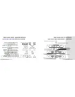
features  and  specifications 

MONO BLOCK AMPLIFIER

 MXAl600 

• 

MXA3000D 

pn1r •iwli• 

Stiffly regulated PWM power supplies. MOSFET switx:hes maintain 
rated power over a wide range 

of 

battery voltages. 

•It 11nic c1ntral 

Wl16n Ille 

sub 

sonic 

selector switch is in 

"ON" mode, 

lllis filter control 

permits continuously variable adjustment from 10 to 100Hz. 

.._ ltDllll 

lnal c1ntral 

This 

control permil!J adjustment of 

Ille bass 

level up to an increase of 

approximately up to 18d8. 

c,_ IDW pm filtlr 

Adjustallle from 

40Hz to 250Hz 

with a slope 

of 24dB 

per octave.This 

al lows for the adjustment of the upper point 

of 

the frequency bandwidth 

and the respective subwooter. 

prDIHtiDn ciraitr, 

Protection against thermal, overload and short circuit conditions. 

.-.111m switch 

Allows you to change the phase 

of 

your subwooter tram 

degree to 

180 

degrees 

to 

help compensate from liming difference between drivers. 

AUX 

li11 a.tpull 

This 

amp features RCA jacks for AUX line outputs. Use these 

outputs. Use these for unlimited system expansion to Ille 

next MAK. 

panr 

l!D  This 

inl1icator 

is 

illuminated in GREEN when power 

is 

applied. 

prDtlcli11 

l!D  This 

inl1icator is illuminated in RED when Ille 

built-in protection 

circuitry 

is actirated. 

pllllll' 

1... 

The 

fuse 

protecls the amplifier 

and 

your 

cats 

electrical syslr)m from s/lort 

circuit 

conditions. 

pn1r terminlll 

use 

lllese 

connectors to deliver power. grounl1, and remote tum-on control 

to Ille amplifier. 

111a111r -•IClllrs 

These terminals am to guarantee high conl1uclivity anl1 minimum signal 

Joss. 

Lanzu MAX  OWlllER'S  MANUAL 

autput pawer 

14Av 

DC, 5111z 

RMS l'ortfll at@ 

Dlnm 

RMS l'ortfll at@ 2 Dlnm

ltfaxl,,,.. "°""' ,,,,,,,,,,

•XA161D

115WMONO 
215WMONO 
2fllJWMONO 

MXA30BOD 

2SOWMONO 

385WMONO 
3(}(J()WMONO 

frequency response 

--

20 

Hz-250 Hz ( ±3dB) 

--

input impedance 

10K Ohms

input sensitivity 

power supply valtage 

min speaker Impedance 

TJl.D 

S/I 

ration

cross filter 

bass 

boast

sub sonic filter 

fuse 

dimensions (W 

L) 

-

lnchel 

--

200mV-6V Adjustable 

--

14.4V 

DC 

Neg. Ground (10.5-16V)

2-40hms 

1-40hms 

0.1% 

>90d8 

40Hz-250Hz 

0-+18d8 
10-100Hz 

25A 

210 x 43.5 x 305 

10.63x1.11x12 

210 x 43.5 x 330 

10.63x1.11 x 13 

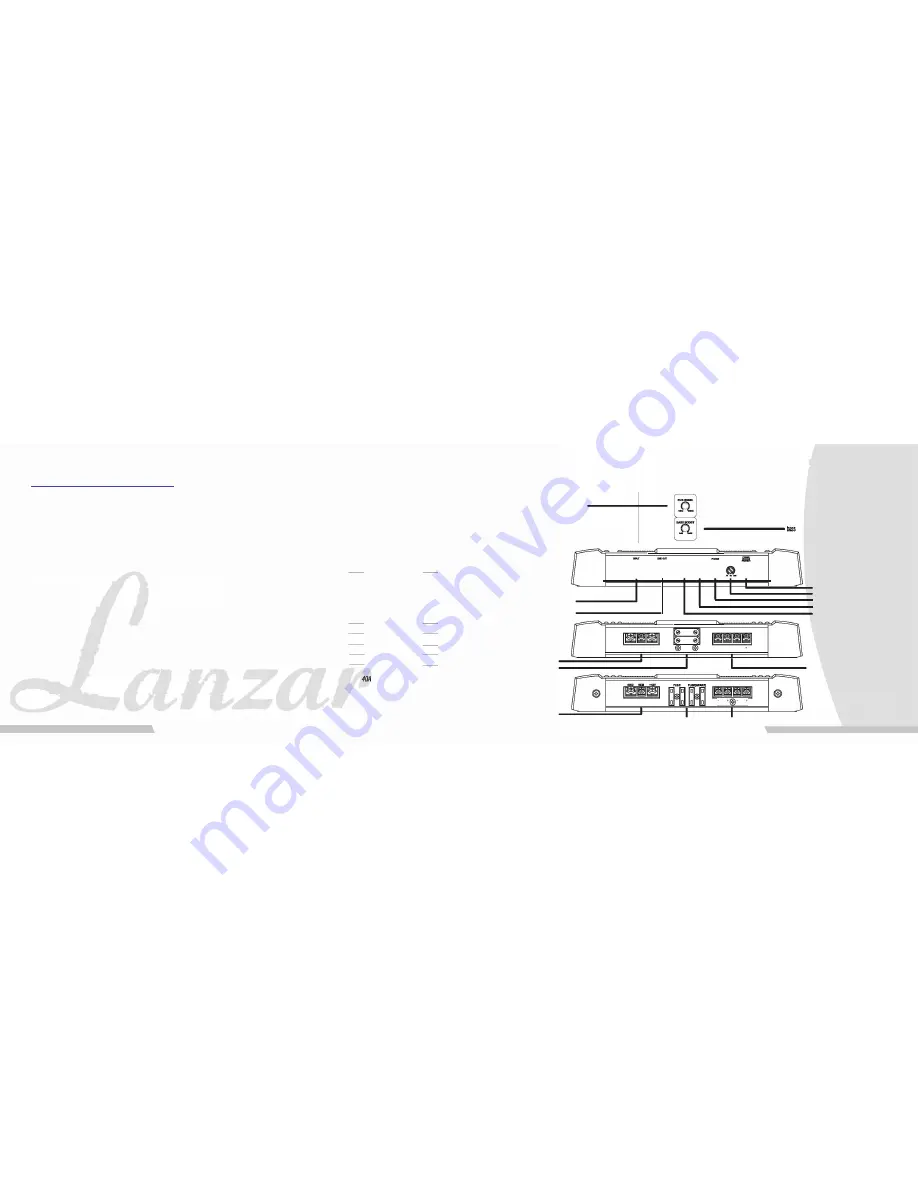
sub sonic level control 

line level inputs 

line level output s 

power terminals 

power fuse 

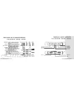
features  and  controls 

MONO  BLOCK  AMPLIFIER  MXAl600 

• 

MXA3000D 

-

©

®

boost level control 

--· 

®®©© 

� 

� 

�  lljllQ

�"'m

HO 

AEll 

+1JV 

(§) 

FUIE 

(§) 

-

� 

� 

C5 

©

®

-

·

@

-

power/protection 

LEO 

low pass frequency control 
phase  shift  switch 
sub  sonic  switx:h 
input level control 

speaker connections 

power terminals 

power fuse---------------

--------- speaker connections 

L•nzu MAX  OWNER'S  MANUAL 

Summary of Contents for MXA224

Page 1: ... NIXA254 NIXA2 4 NIXA4_ 4 NIXA 00 NIXA3000D RICAN RAFTED PERFORMANCE ...

Page 2: ...cuitry isactirated pllllll 1 The fuseprotecls the amplifierandyourcatselectrical syslr mfrom s lort circuit conditions pn1rterminlll use llleseconnectors to deliverpower grounl1 and remote tum on control to Ille amplifier 111a111r IClllrs These terminalsam to guarantee high conl1uclivityanl1 minimum signal Joss Lanzu MAX OWlllER S MANUAL autput pawer 14Av DC 5111z RMSl ortfllat 4Dlnm RMSl ortfllat...

Page 3: ...these forunlimitBdsystem expansion to the nextMAX Tllis indicatoris illuminatsd in GREEN whtlltpower isapplied TiiisIndicatorIs11 umlnallidIn REDwhenthe built Inprotutlonclrcull1y isactirallid 1116fuSBprot9ctsth8amplifitNandyourcar s8l6cttfca system fromshort clrculrconditions Use these connectolStodeliverpower ground and mmolli tum on control ta th11amplifiBr 1mi 1tpna HAlll 1111z _ 1111tU _ _tU ...

Page 4: ...ne outputs Use these for unlimited system expansion to lfJenextMAX pnw LED This indicator isillumina ed in GREENwhen power isapplied lll Gl ctlan LED This indicator isillumina ed in RED when the built in protection circuitry is actira ed fllll The fusepro 1Jcls theamplifieranl1yaur cars electrical systemfrom short circuitconditions p 111111 11 use theseconnectors to deliver power ground and remote...

Page 5: ...ts Use these for unlimitedsyslllm expansion to the nextMAX LED This indir ator is illuminated in GREENwhen power Isapplied pndlctl LED This indir atorisilluminated in RED whenthebuilt in pro Bet on cirr uilly isactirated fme Thefuseprotectstheamplifierandj Otlfra seltJCITica sys Bmfromshort cirr vitcondiUons 11 llrllll ll UsethesecoonectrJ sto deliVfJIpower ground andremolBtum oncontrol to theampl...

Page 6: ...GND IE t2Y lf HIH fl 0 I head unit I c I c I 1WJim1 R t L t e 12Vbattery Mano block amp MXAl600 MXA3DDDD Lanzar MAX OWlll R S MANUAL I J I I head unit electrical connections q ch amp MXA i 11 i 1 11imli1 jl1mmmm1 FUllE CH4 Cl 3 Cllh CMt I 10 I 12Vbattery tonmo rurn on 12V Lanzar MAX OWNER S MANUAL 11 ...

Page 7: ... low level lnpute ualne low level lnputa head unit Toasecondamplifier _ _____ _ YAdaptors ua1ne high level lnputa ualne high level lnputa headunit head unit from speaker terminals DTlfRMAXMl UFlER HI LEVEL INPUT ADAPTOR ti from speaker terminals ANOTHERMAX AMPLIFIER Lanzar MAX OWllER S MANUAL Lanzar MAX OWN ER S MAN UAL ...

Page 8: ... OWllER S MANUAL a 0 ANOTHERMAXAMPLIFIER t mono Input connections 2 ch amp MXA241 q MXA2s q MXA2e q ualne low level Input M UT LllllOUI IGHC X OWU a oino mu o rOr head unit To a second amplifier iiii YAdaptors ualne high level lnputa head unit HI LEVEL INPUT ADAPTOR _ __ from speaker terminals ANOTHERMAXAMPLIFIER Lanzar MAX OWNER S MANUAL ...

Page 9: ...iEJ 2 CH Input connectlona ualng low level lnpute Lanzar MAX OWlll R S MANUAL CH Ploatlng ground cannectlona HI LEVEL INPUT ADAPTOR to iiii FRONT L R L R REAR from speakerterminals high level Input connections iq ch amp MXA iq1 iq CH hameaa wiring Par common eruund connectlona CH 112 REAR L R L from speakerterminals Cll 314 R FRONT Lanzar MAX OWNER S MANUAL ...

Page 10: ... Brldeed mono Output mode Lanz MAX OWlll R S MANUAL aJ1 1 speaker MINIMUM SPEAKER IMPEDUCE 40HMS mono Input connections q ch amp MXA ill ll ill I CH mono Input cannectlana ualng low level Inputs LEFT FRONTAudio Outputs RIGHT REAR Audio Out uts LEFT REAR Audio Outputs 2CH mono Input connecaana ualng low level Inputs Y adaptors L L nz MAX OWlll R S MANUAL ...

Page 11: ... L R FRONT speakers speakers L MINIMUM SPEAKER IMPEDANCE 40HMS speaker connections ch amp MXA I 2 CH Bbrea Output made with mono Bridged ubwaoPer Output r J I 11111 1 11 1 FUIE Clt4 CHI Clt2 Clt1 J 1 6 SUBWOOFER I I 4i L RC e SPEAKERS MINIMUM SPEAKER MPEDANCE 4OHMS Lanzar MAX OWNER S MANUAL ...

Page 12: ...crews inserted in each of the mounting holes to mark the mounting surface If the mounting surface 1s carpeted measure the hole centers and mark with a felt tip pen Before atte ing ta drill the mounting hales take note at 11J wires lines ar other devices in pur vehicle which mlJ lie located llelllnd the mauntllg surface Then drill pilot holes in the mounting surface for the mounting screws and inse...

Page 13: ...irm that the amplifier and any other signal sources head unit etc are properly grounded If the noise is a clicking or popping noise whose rate follows the engine speed this usually means that the vehicle is equipped with resistor spark plugs and wires or that the ignition is in need of service Check the rounting of the speaker and input wires to make sure they are not adjacent to wires which inter...

Reviews: