LPMVC-CL025M Manual
More than Imaging – Laon People
17
2016-03-04
4.
Camera Interface
4.1.
General Description
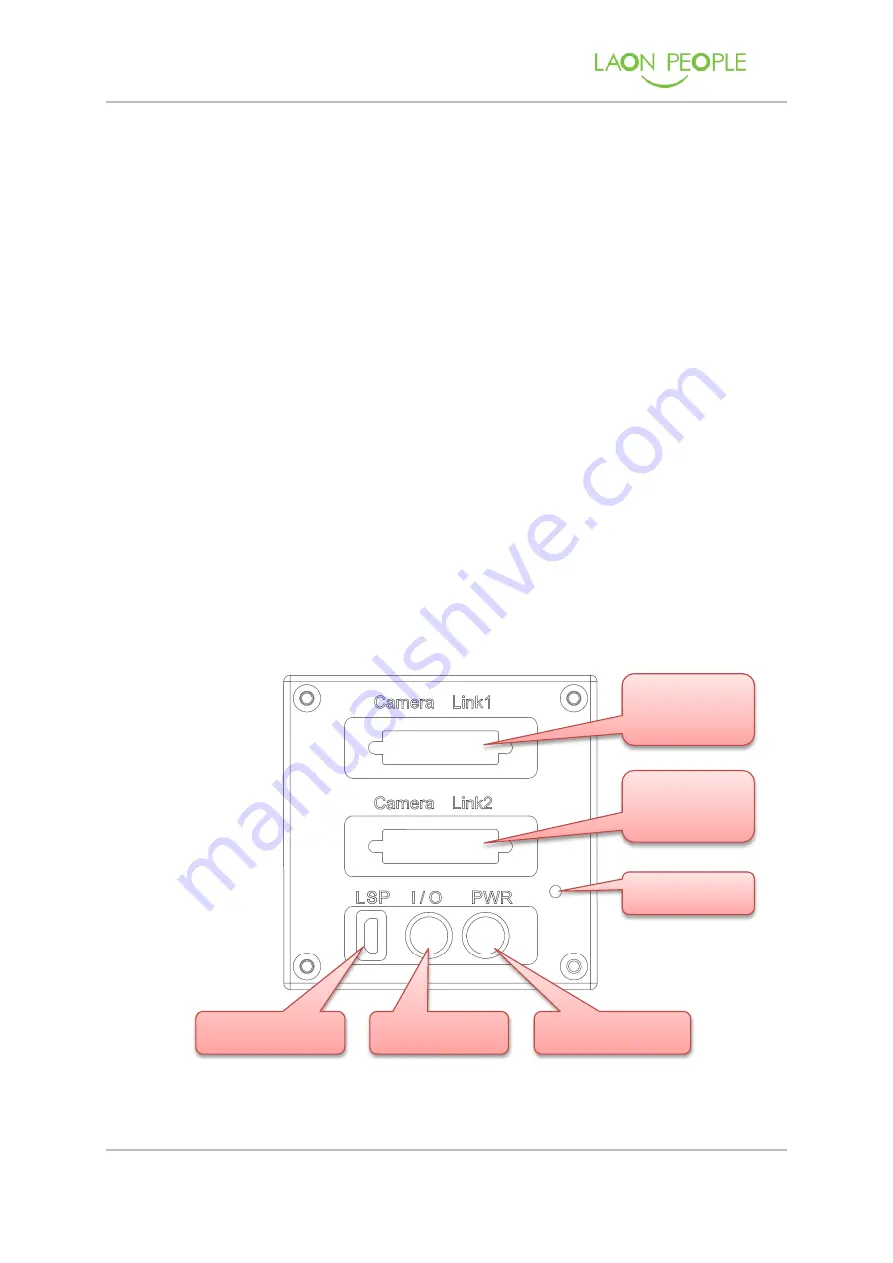
LPMVC-CL025M camera connects and communicates with external equipment through
the following 4 connectors, and LPMVC-CL025M indicates the status of the camera by
the camera’s rear LED.
①
Camera Link Connector 1
: 26-Pin Mini D Ribbon (MDR) female connector used to
transmit image data, control data, and configuration data.
②
Camera Link Connector 2
: 26-Pin Mini D Ribbon (MDR) female connector used to
transmit image data.
③
Status LED
: Dual-Color LED used to display power, camera operation status.
④
JTAG Connector
: USB Micro-B Type connector, But pins of connector are connected
to JTAG of FPGA
⑤
I/O Connector
: 4-Pin Push-Pull female connector used to external trigger input and
strobe output
⑥
Power Connector
: 6-Pin Push-Pull male connector used to provide power to the
camera.
Figure 5. Back Panel of LPMVC-CL025M
1. Camera Link
Connector 1
2. Camera Link
Connector 2
3. Status LED
6. Power Connector
5. I/O Connector
4. JTAG Connector


