background image

13 

LA-ON-LCD

-V.09


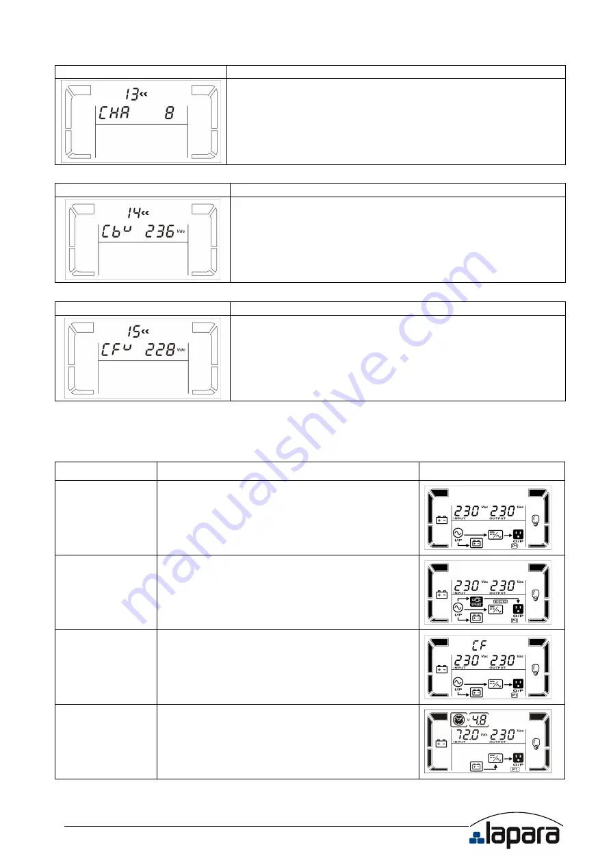
13: Charger maximum current setting 

Interface 

Setting 


Parameter 3: Set up the charger maximum current.   
1/2/4/6/8: setting the charger maximum current 1/2/4/6/8* in 
Ampere. (Default: 8A)   
*Note: This setting is only available for super charger. 


14: Charger Boost voltage setting 

Interface 

Setting 


Parameter 3: Set up the charger boost voltage.   
225-240: setting the charger boost voltage from 2.25 V/cell to 
2.40V/cell. (Default: 2.36V/cell)   


15: Charger Float voltage setting 

Interface 

Setting 


Parameter 3: Set up the charger float voltage.   
220-233: setting the charger float voltage from 2.20 V/cell to 
2.33V/cell. (Default: 2.28V/cell) 


00: Exit setting 


3.6. Operating Mode Description 

Operating mode  Description 

LCD display   

Online mode 

When the input voltage is within acceptable 
range, UPS will provide pure and stable AC 
power to output. The UPS will also charge the 
battery at online mode.   


ECO mode 

Energy saving mode:   
When the input voltage is within voltage 
regulation range, UPS will bypass voltage to 
output for energy saving.   


Frequency 
Converter mode 

When input frequency is within 40 Hz to 70 
Hz, the UPS can be set at a constant output 
frequency, 50 Hz or 60 Hz.    The UPS will still 
charge battery under this mode. 


Battery mode 

When the input voltage is beyond the 
acceptable range or power failure and alarm is 
sounding every 5 seconds, UPS will backup 
power from battery.   


Summary of Contents for UPS 1K

Page 1: ...Online UPS 1K 2K 3K Uninterruptible Power Supply System USER MANUAL EN ...

Page 2: ...s 2 2 Installation and setup 3 2 1 Rear panel view 3 2 2 Setup the UPS 4 3 Operations 7 3 1 Button operation 7 3 2 LCD Panel 7 3 3 Audible Alarm 9 3 4 LCD display wordings index 9 3 5 UPS Setting 10 3 6 Operating Mode Description 13 3 7 Faults Reference Code 14 3 8 Warning indicator 14 4 Troubleshooting 15 5 Storage and Maintenance 16 6 Specifications 17 ...

Page 3: ...r trip over them Do not connect domestic appliances such as hair dryers to UPS output sockets The UPS can be operated by any individuals with no previous experience Connect the UPS system only to an earthed shockproof outlet which must be easily accessible and close to the UPS system Please use only VDE tested CE marked mains cable e g the mains cable of your computer to connect the UPS system to ...

Page 4: ...d persons must be kept well away from the batteries Caution risk of electric shock The battery circuit is not isolated from the input voltage Hazardous voltages may occur between the battery terminals and the ground Before touching please verify that no voltage is present Batteries may cause electric shock and have a high short circuit current Please take the precautionary measures specified below...

Page 5: ...le Model Type Model Type 1K Standard 1K L Long run 2K 2K L 3K 3K L 2 1 Rear panel view 1K L TOWER 2K L TOWER 3K L TOWER 1 Programmable outlets connect to non critical loads 2 Output receptacles connect to mission critical loads 3 AC input 4 Input circuit breaker 5 Network Fax Modem surge protection 6 Emergency power off function connector EPO 7 USB communication port 8 RS 232 communication port 9 ...

Page 6: ...aintain maximum altitude of 1000m to keep UPS normal operation at full load UPS If it s used in high altitude area please reduce connected load Altitude derating power with connected loads for UPS normal operation is listed as below 4 Place UPS It s equipped with fan for cooling Therefore place the UPS in a well ventilated area It s required to maintain minimum clearance of 100mm in the front of t...

Page 7: ... power cord is attached to the UPS The input plug is a NEMA 5 15P for 1K and 1K L models NEMA 5 20P for 2K and 2K L models Note For Low voltage models Check if the site wiring fault indicator lights up in LCD panel It will be illuminated when the UPS is plugged into an improperly wired utility power outlet Refer to Troubleshooting section Step 3 UPS output connection For socket type outputs there ...

Page 8: ... pin 1 and pin 2 closed for UPS normal operation To activate EPO function cut the wire between pin 1 and pin 2 Step 7 Turn on the UPS Press the ON Mute button on the front panel for two seconds to power on the UPS Note The battery charges fully during the first five hours of normal operation Do not expect full battery run capability during this initial charge period Step 8 Install software For opt...

Page 9: ...tton Confirm selection key Press this button to confirm selection in UPS setting mode Select Button Switch LCD message Press this button to change the LCD message for input voltage input frequency battery voltage output voltage and output frequency It will return back to default display when pausing for 10 seconds Setting mode Press and hold this button for 3 seconds to enter UPS setting mode when...

Page 10: ...ad level by 0 24 25 49 50 74 and 75 100 Indicates overload Indicates the load or the UPS output is short circuit Programmable outlets information Indicates that programmable management outlets are working Mode operation information Indicates the UPS connects to the mains Indicates the battery is working Indicates the bypass circuit is working Indicates the ECO mode is enabled Indicates the Inverte...

Page 11: ...nding every 10 seconds 3 4 LCD display wordings index Abbreviation Display content Meaning ENA Enable DIS Disable ESC Escape HLS High loss LLS Low loss BAT Battery BAH Battery AH CHA Charger current CBV Charger boost voltage CFV Charger float voltage CF Converter ON ON EP EPO TP Temperature CH Charger FU Bypass frequency unstable EE EEPROM error FA Fan failure BR Battery Replacement ...

Page 12: ...ing output voltage 100 present output voltage is 100Vac 110 present output voltage is 110Vac 115 present output voltage is 115Vac 120 present output voltage is 120Vac Default 127 present output voltage is 127Vac 02 Frequency Converter enable disable Interface Setting Parameter 2 3 Enable or disable converter mode You may choose the following two options CF ENA converter mode enable CF DIS converte...

Page 13: ...127 VAC models the setting voltage in parameter 3 is from 3V to 12V of the nominal voltage Default 6V 06 Bypass enable disable when UPS is off Interface Setting Parameter 3 Enable or disable Bypass function You may choose the following two options ENA Bypass enable DIS Bypass disable Default 07 Bypass voltage range setting Interface Setting Parameter 2 3 Set the acceptable high voltage point and a...

Page 14: ...eter 3 Enable or disable programmable outlets ENA Programmable outlets enable DIS Programmable outlets disable Default 10 Programmable outlets setting Interface Setting Parameter 3 Set up backup time limits for programmable outlets 0 999 setting the backup time limits in minutes from 0 999 for programmable outlets which connect to non critical devices on battery mode Default 999 11 Autonomy limita...

Page 15: ...m 2 20 V cell to 2 33V cell Default 2 28V cell 00 Exit setting 3 6 Operating Mode Description Operating mode Description LCD display Online mode When the input voltage is within acceptable range UPS will provide pure and stable AC power to output The UPS will also charge the battery at online mode ECO mode Energy saving mode When the input voltage is within voltage regulation range UPS will bypass...

Page 16: ...Over load 43 Inverter voltage Low 13 x Charger failure 45 x 3 8 Warning indicator Warning Icon flashing Alarm Low Battery Sounding every 2 seconds Overload Sounding every 2 seconds Battery is not connected Sounding every 2 seconds Over Charge Sounding every 2 seconds Site wiring fault Sounding every 2 seconds EPO enable Sounding every 2 seconds Over temperature Sounding every 2 seconds Charger fai...

Page 17: ... incorrectly connected Check if all batteries are connected well Fault code is shown as 27 and the icon is lighting on LCD display and alarm is continuously sounding Battery voltage is too high or the charger is fault Contact your dealer Fault code is shown as 28 and the icon is lighting on LCD display and alarm is continuously sounding Battery voltage is too low or the charger is fault Contact yo...

Page 18: ...o replace the battery The icon and the warning code flashing on LCD display and alarm is sounding every 2 seconds Fan is locked or not working Check fans and notify dealer Fault code is shown as 45 on LCD display At the same time alarm is continuously sounding The charger does not have output and battery voltage is less than 10V PC Contact your dealer 5 Storage and Maintenance Operation The UPS sy...

Page 19: ... Battery Type 12V 7AH 12V 7AH 12V 9AH Numbers 3 6 6 Typical Recharge Time 4 hours recover to 90 capacity Charging Current máx 1 5 A max Charging Voltage 41 0 VDC 1 82 1 VDC 1 Long run Model Battery Type Depending on the capacity of external batteries Charging Current máx 1 2 4 6 8 A Selectable via LCD setting Charging Voltage 41 0 VDC 1 82 1 VDC 1 CONNECTORS Current outputs 4xIEC 8xIEC 6xIEC Termi...

Page 20: ...SAI Online 1K 2K 3K Sistema de Alimentación Ininterrumpida Manual de usuario ES ...

Reviews: