background image


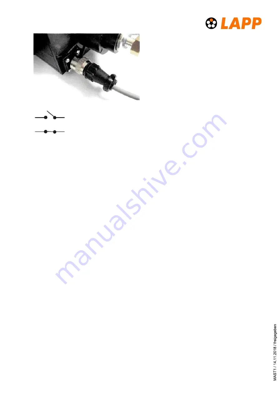
The 2 pole connector mounted on the rear 
is connected to a micro-switch inside the 
unit: If all connectors are in place and the 
unit is locked, the micro switch is locked A 
complete assembly instructions for this 
connector are shown at the end of this doc-
ument. 


Micro switch with POWERLOCK BOX - open 
 
Micro switch with POWERLOCK BOX - closed 


4 Installation and usage  

4.1 Warnings 


This box should only be operated by suitably qualified persons. 


Only original POWERLOCK connectors should be used with this unit. The use of non-
approved connectors may cause damage to the box and will invalidate any warranty. 


Ensure that the current rating of the cables and connectors being used are suitable for 
the current rating of the POWERLOCK BOX and connected supply. 


Do not connect / disconnect under load! 

4.2 Connection with cable connectors 

The necessary mating connectors have to be ordered separately and are not part of the deliv-
ery. Recommended cross-sections are printed on the rear of the box: 

400


- 120 mm² and 660 A – 240 mm². 

 
1.


Use the Allen wrench to open the cover (version with safety cover). 

2.


The POWERLOCK connectors are plugged sequentially in a row. Starting on the left with 
the Ground/Earth connection (Green) going to the right with N, L1, L2, L3. 

3.


Insert the Ground (Green) connector, aligning the “PUSH” arrow on the label of the con-
nector in a 12 o´clock position. Fully insert the connector until it bottoms in the cavity 
and turn through 45 degrees clockwise until the connector locks with an audible „click‟. 

4.


Repeat the above process for the Neutral connector and the rest of the connectors. If at 
any time a connectors does not rotate fully, check if the previous connector is fully 
turned. 

5.


The lock is located to the right of the L3 connector on the front panel. The needed square 
drive key is provided.  

Summary of Contents for POWERLOCK BOX

Page 1: ...e control cabinet buliding 2 3 1 Mechanical mounting 2 3 2 Power installation 3 3 3 Connector for remote sensing 3 4 Installation and usage 4 4 1 Warnings 4 4 2 Connection with cable connectors 4 5 Technical data 5 6 Maintenance disposal 5 7 Appendix Mounting of the micro switch connector 6 ...

Page 2: ...ld contain the following 1x POWERLOCK BOX 1x 6 mm Allen wrench 1x 2 pole cable connector for remote sensing 1x Operating Maintenance guide 3 Mounting at the control cabinet building 3 1 Mechanical mounting POWERLOCK BOXES are designed for standard 19 rack systems or to dedicated panel mounts within buildings or remote cabinets It is recommended that M6 screws bolts and flat washers are used and ti...

Page 3: ...ces are adopted Power installation M12 threaded posts on the rear of the unit are for connecting power ca bles fitted with cable lugs Each position is marked on the back of the box E Ground N L1 L2 L3 The threaded posts have a spring washer and nut that should be tightened to a torque of 27 5 Nm min to 31 4 Nm max It is recommended that insulated spanners are used when making these connections 3 3...

Page 4: ...ection with cable connectors The necessary mating connectors have to be ordered separately and are not part of the deliv ery Recommended cross sections are printed on the rear of the box 400 120 mm and 660 A 240 mm 1 Use the Allen wrench to open the cover version with safety cover 2 The POWERLOCK connectors are plugged sequentially in a row Starting on the left with the Ground Earth connection Gre...

Page 5: ...ed IP65 with closed safety cover box with cover Weight 3 25 kg without cover 3 75 kg with cover Flammability rating UL94 V0 Mating cycles 500 6 Maintenance disposal Mounting and maintenance should only be performed by qualified staff Periodic greasing of the O Ring seals on the connector ports is recommended The POWERLOCK BOX should regularly be inspected for damage including a visual in spection ...

Page 6: ...ll clamping parts 5 Pass the wires cable through the endbell 6 Insert the insulator into the coupling nut 7 Insert contacts into cavaties A C Position B D are preloaded to prevent a wrong positioning of the contacts 8 Screw the endbell to the connector and hand tighten 9 Select and fit a suitable clamp bar for your wire cable and tighten screws U I Lapp GmbH D 70565 Stuttgart Germany www lappgroup...

Reviews: