


6.
Remove the key. All connectors are now locked in place and cannot be removed until the
box is unlocked.
7.
To remove the connectors, ensure that the power is turned off and reverse the above pro-
cedure.
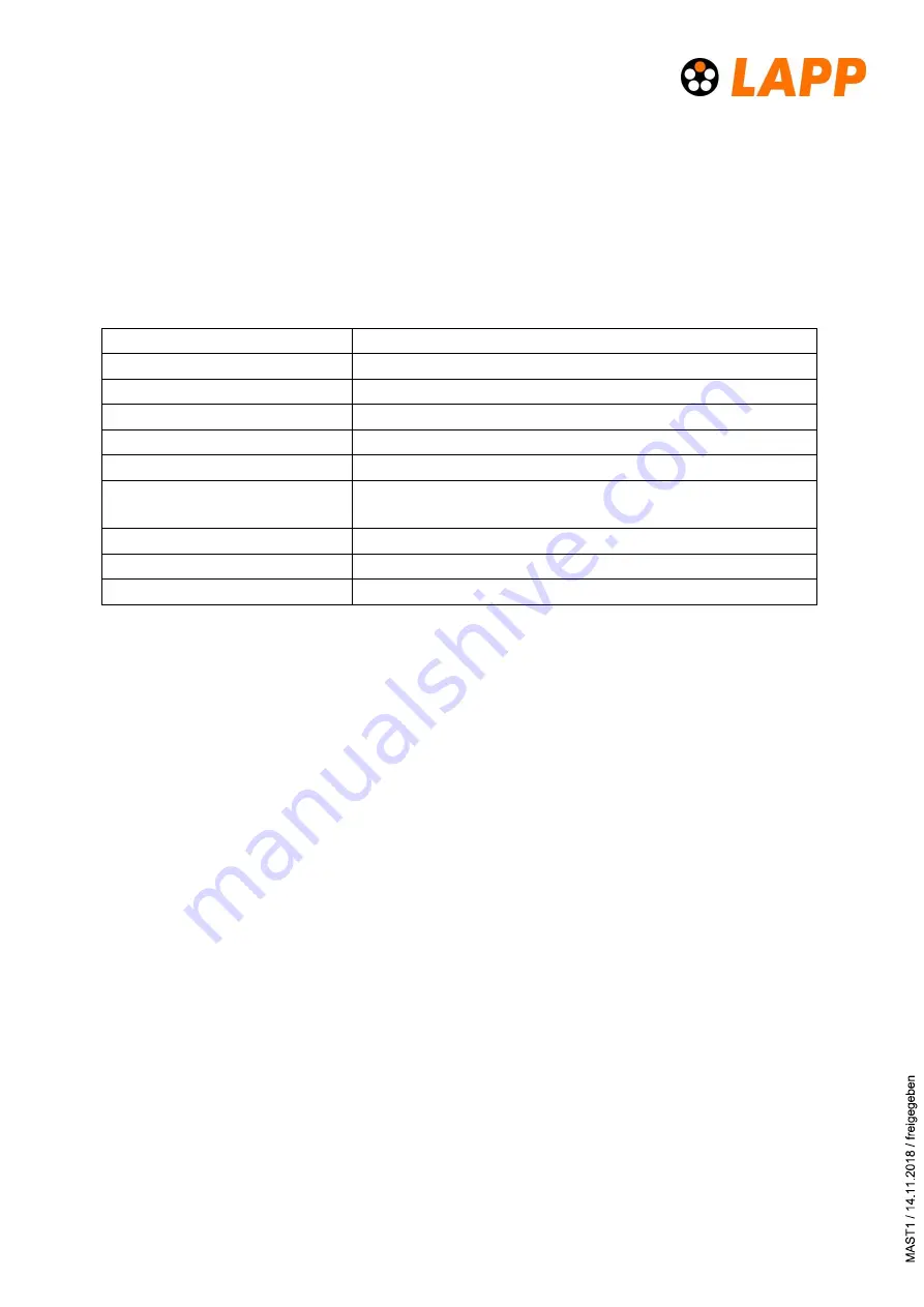
5 Technical data
The POWERLOCK BOX is CE labeled and fullfills all relevant requirements.
Current rating
400 or 660 ampere (depending on the version)
Voltage rating
1000V AC /1500V DC
Dielectric strength
9500 V DC
Micro-switch operating voltage
125 V AC max.
Micro-switch operating current
5 A
Operating temperature
- 30°C to +85°C
Environmental protection
IP65 connectors plugged
IP65 with closed safety cover (box with cover)
Weight
3,25 kg (without cover) 3,75 kg (with cover)
Flammability rating
UL94 – V0
Mating cycles
500
6 Maintenance & disposal
Mounting and maintenance should only be performed by qualified staff.
Periodic greasing of the O-Ring seals on the connector ports is recommended.
The POWERLOCK BOX should regularly be inspected for damage, including a visual in-
spection of the source contacts.
Periodic retention testing of PS (Power Source) contacts is recommended to confirm
that contact life has not been exceeded
Disposal:
After use the device should be disposed of in accordance with national or local author-
ity guidelines.
The carton and its packing are recyclable and should be disposed according to na-
tional or local authority guidelines.


