background image

6

English

High pressure hose

G

• 

TIGHTEN AND CHECK ALL THE FITTINGS FOR CONNEC-
TION BETWEEN PUMP, FLEXIBLE HOSE AND SPRAY GUN 
BEFORE USING THE EQUIPMENT.

• 

ALWAYS  USE  THE  FLEXIBLE  HOSE  SUPPLIED  WITH 
STANDARD KIT. THE USE OF ANY ACCESSORIES OR 
TOOLING  OTHER  THAN  THOSE  RECOMMENDED  IN 
THIS MANUAL, MAY CAUSE DAMAGE OR INJURE THE 
OPERATOR.

• 

THE FLUID CONTAINED IN THE FLEXIBLE HOSE CAN 
BE VERY DANGEROUS. HANDLE THE FLEXIBLE HOSE 
CAREFULLY.  DO  NOT  PULL  THE  FLEXIBLE  HOSE  TO 
MOVE THE EQUIPMENT. NEVER USE A DAMAGED OR 
A REPAIRED FLEXIBLE HOSE.

The high speed of travel of the product in the 
hose can create static electricity through di-

scharges and sparks. It is suggested to earth 
the equipment. 

The pump is earthed through the earth cable of the supply. 
The gun is earthed through the high pressure flexible hose.  
All the conductors near the work area must be earthed.

• 

NEVER SPRAY OVER FLAMMABLE PRODUCTS OR SOL-
VENTS IN CLOSED PLACES.

• 

NEVER USE THE TOOLING IN PRESENCE OF POTEN-
TIALLY EXPLOSIVE GAS.

Always check the product is compatible with 
the materials composing the equipment 

(pump, 

spray gun, flexible hose and accessories)

 with 

which  it  can  come  into  contact.  Never  use 

paints or solvents containing halogen hydrocarbons 

(as the 

methylene chloride)

If these products come into contact with aluminium parts can 
provoke dangerous chemical reactions with risk of corrosion 
and explosion. 

IF THE PRODUCT TO BE USED IS TOXIC, AVOID INHALATION 
AND CONTACT BY USING PROTECTION GLOVES, GOGGLES 
AND PROPER FACE SHIELDS

TAKE PROPER SAFETY MEASURES FOR THE PROTECTION 
OF HEARING IN CASE OF WORK NEAR THE PLANT.

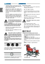
Electrical safety precautions

• 

Check the "ON/OFF" switch is on the "OFF" position before 
connecting the cable to the mains.

• 

Never carry a plugged-in equipment.

• 

Disconnect the equipment before storing it and before per-
forming any maintenance operation or replacing of acces-
sories. 

• 

Do not carry the equipment neither unplug it by pulling the 
electric cable.


Protect the cable from heat, oil and sharp edges.

• 

When the tool is used outdoors, use only an extension cable 
suited for outdoor use and so marked.

Never  attempt  to  tamper  with  the  calibre  of 
instruments.

•     Take care when the pumping rod is moving. 
 

Stop the machine whenever someone is within its vicinity.

• 

Repairs of the electrical equipment should only be carried 
out by skilled personnel, otherwise considerabledanger to 
the user may result.

SETTING-UP

CoNNECTIoN oF THE FLExIBLE HoSE To THE GUN

•   Connect the high pressure flexible hoses  to the pump and the 

guns  tightening the fittings strongly 

(the use of two wrenches 

is suggested)


NEVER 

use sealants on fittings threads.


It is 

ADVISED 

to mount a high pressure manometer at the 

pump outlet 

(see on page "Accessories")

 to read the product 

pressure.

•   It is recommended  to use the hose provided  with the standard  

kit.


NEVER 

use a damaged or a repaired flexible hose.  

Summary of Contents for K-2

Page 1: ...Airless LineStriper ENGLISH OPERATING AND MAINTENANCE INSTRUCTION OPERATING AND MAINTENANCE INSTRUCTION PAINTING EQUIPMENT Ed 005 11 10 ...

Page 2: ......

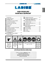
Page 3: ...RIES p 24 HIGH PRESSURE PAINTING EQUIPMENT HIGH PRESSURE PAINTING EQUIPMENT WE ADVISETHE USE OFTHIS EQUIPMENT ONLY BY PROFESSIONAL OPERATORS ONLY USETHIS MACHINE FOR USAGE SPECIFICALLY MENTIONED INTHIS MANUAL Thank you for choosing a LARIUS S R L product As well as the product purchased you will receive a range of support services enabling you to achieve the results desired quickly and professiona...

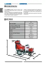
Page 4: ...without air from this process derives the term airless The pump is controlled by an motor coupled with a reduction gear Acamshaftandaconnectingrodallowtoobtainthereciprocating motionnecessarytotheworkingofthe pumpinggroup diaphram The piston movement produces a depression The product is sucked pushed towards the pump outlet and then sent to the gun through the flexible hose A mechanical device all...

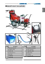
Page 5: ...HE EQUIPMENT Pressure control knob Reduction casting Suction Tube High pressure hose Airless gun Product tank Suction filter Description POS 8 9 10 11 12 13 High pressure manometer Airless manual gun Trigger safety clamp Battery charger Drain valve Recirculation tube Description ...

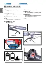
Page 6: ... D3 Pull the lever to release the motors brake D4 LED Indicates whether the power to the panel is on or off D5 Key operated selector switch Used to switch on machine Steerage lever Motor brake release Gun control lever D6 Indicator Indicates the charge in the electrical battery D7 Adjustment knob Used to progressively adjust the machine s running speed D8 Direction selector Allowstheusertoselectth...

Page 7: ...allthoserisksstemmingfromacci dents abouttheuseofsafetydevicesfor their own safety and about the general rulesforaccidentpreventionincomplian cewithinternationalregulationsandwith the laws of the country where the plant is used The behaviour of the employees shall strictlycomplywiththeAccidentpreven tion AND ALSO ENVIRONMENTAL regulations in force in the country where the plant is installed and us...

Page 8: ...uschemicalreactionswithriskofcorrosion and explosion IFTHE PRODUCTTO BE USED ISTOXIC AVOID INHALATION ANDCONTACTBYUSINGPROTECTIONGLOVES GOGGLES AND PROPER FACE SHIELDS TAKE PROPER SAFETY MEASURES FORTHE PROTECTION OF HEARING IN CASE OF WORK NEAR THE PLANT Electrical safety precautions Check the ON OFF switch is on the OFF position before connecting the cable to the mains Never carry a plugged in e...

Page 9: ...the electric motor Now the machine is ready Should you use water paints besides the solvent wash a wash with soapy and then clean water is suggested Insert the gun trigger lock and assemble the nozzle PREPARATION OFTHE PAINT Make sure the product is suitable to be used with a spray gun The use of non compliant products causes damage to the machine thus annulling the guarantee only use specific fil...

Page 10: ...int let the gun advance sideways right left when spraying Always paint with regular parallel bands coats Keepasafetyandconstantdistancebetweenthegunandthe supporttobepaintedandalsokeepyourselvesperpendicular to it Never point the spray gun at yourselves or at other people The contact with the casting can cause serious injuries In case of injuries caused by the gun casting seek immediate medical ad...

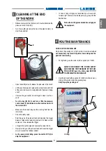
Page 11: ...e residual solvent As the pump starts idling press the switch OFF 0 to stop the equipment I CLEANING ATTHE END OFTHE WORK Reduce pressure to the minimum turn counterclockwise the pressure control knob I1 Turn the key I2 placed on the box of the electric motor to stop the equipment J ROUTINE MAINTENANCE CHECK ONTHE PACKING NUT Daily check the packing nut is tight in order to avoid wastes but not ex...

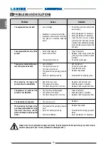
Page 12: ...oduct is too dense The filter of the gun butt is too fine The nozzle is worn The gaskets of the pumping group are worn Suction or delivery valve dirty Drain valve defective Check the correct connection to the power supply Verify and replace it if necessary Verify and replace it if necessary Open the drain valve to release pressure in the circuit and stop the machine Disassemblethepumping group and...

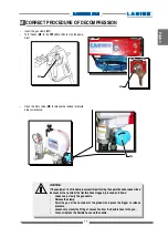
Page 13: ...vedescribed because of the nozzle or the flexible hose clogged proceed as follows Loosen very slowly the gun nozzle Release the clamp Point the gun at the container of the product and press the trigger to release pressure Loosen very slowly the fitting of connection from the flexible hose to the gun Clean or replace the flexible hose and the nozzle Open the drain valve M3 to release the residual p...

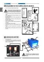
Page 14: ...e from the pumping group by loosening the locknut Unscrew the upper packing nut Unscrewthesuctionvalveandcleanand orreplaceitsparts if necessary Extract the piston rod from the bottom Disassemble the piston rod and replace the gaskets group if worn If necessary remove the upper gaskets for their replace ment See the exploded view of the pumping group for the correct assembly Lock nut Dowel pins Cl...

Page 15: ...ipment does not suck materials remove the product tank Open the drain valve P3 Disassemble the pumping group as shown on the previous chapter Pressure sensor Pressure pin Remove the pressure sensor from its housing and chek if the pin can move If necessary clean thoroughly Check the seals O ring and teflon ring if worn or pinched replace them Disassemblethesupportingblockandcheckthemicroswitch ope...

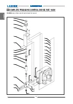
Page 16: ...4 English 30 28 29 12 13 11 11 23 27 25 24 22 20 17 18 16 15 15 19 26 14 10 9 8 7 6 5 4 3 2 1 Q COMPLETE PRESSURE CONTROL DEVICE REf 16350 WARNING always indicate code and quantity for each part required ...

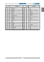
Page 17: ...pport box Control rod Quill Elastic ring Ball Spring Pin Adjusting pin Knob Dowel Label 16336 16335 11955 16334 9287 16333 16331 16332 4077 96090 96028 16037 16042 16280 16312 16307 22059 16310 16313 16311 16306 16304 81017 4060 16303 16309 16315 16301 95210 16308 1 2 3 4 5 6 7 8 9 10 11 12 13 14 15 16 17 18 19 20 21 22 23 24 25 26 27 28 29 30 Code Description Code Description ...

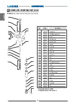
Page 18: ... Pos Packing nut Complete upper seals Dowel Assembly pins Pumping case Screws Piston rod Screws Piston rod Elastic pin Ball Nut Complete lower seals Union Lock nut O ring Pumping cylinder Ball guide Ball O ring Foot valve Pin 16109 16105 96205 16033 16101 33007 33006 16111 16110 91010 16130 16113 16115 16128 16127 16126 16112 98466 16120 16121 16129 16122 1 2 3 4 5 6 7 8 9 10 11 12 13 14 15 16 17 ...

Page 19: ...le ring cod 16108 Red cod 16104 White cod 16124 Steel female ring cod 16106 Steel male ring cod 16116 Steel female ring cod 16118 White cod 16136 Red cod 16114 cod 16132 cod 16105 Red cod 16104 White cod 16124 White cod 16136 Red cod 16114 cod 16133 cod 16115 Lower seals ...

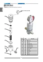
Page 20: ...art required 1 2 3 4 5 6 8 8 7 Manometer 0 400 bar code 33008 Pos Filter tank Spring Standard sieve Standard sieve 100 Standard sieve 200 Sieve support Gasket Filter base Union Dowel 16201 96202 16205 16204 16203 16202 96203 96204 96206 96205 1 2 3 3 3 4 5 6 7 8 Code Description ...

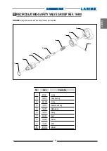
Page 21: ... REF 16400 WARNING always indicate code and quantity for each part required Pos O ring Valve housing O ring Antiextrusion ring Material rod Spring Bush Dowel Knob Dowel 4033 16415 53007 3 16419 16420 16410 46409 16408 16405 90018 1 2 3 4 5 6 7 8 9 10 Code Description ...

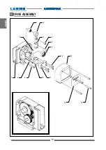
Page 22: ...20 English 1 2 3 4 6 5 16 12 13 14 15 7 8 9 10 11 U DRIVE ASSEMBLY ...

Page 23: ...crew Bushing Closing bracket Screws Cover Screw Tornado label Dowel Battery charger Batteries 6V 240Ah 16024 16025 16040 16026 16028 16019 8029 16029 95623 16027 16030 81032 16031 16036 16045 16023 4605 19461 Code Description Code Description 1 2 3 4 5 6 7 8 9 10 11 12 13 14 15 16 17 18 ...

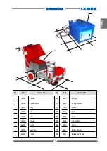
Page 24: ...r Dispersion bell Breaker flux Bell pipe Pipe fitting with spring 16802 18351 18352 18353 18608 1 2 3 4 5 Codice Description Pos Female extension 3 8 male 1 4 Pipe fitting Delivery compensation hose length 15 mt 22028 16058 18026 6 7 8 Codice Description ...

Page 25: ...032 30532 8375 20833 18223 1 1 2 3 4 5 6 7 8 9 10 11 Code Description TYPE D REF 18238 TYPE E REF 18225 N 2PZ TYPE F REF 18225 Type Liner Type E Type F Type D Type D Type D Type D LARIETTE LINER 3000 LINER DALì LINER DRAGON LINER EVEREST K2 Type Type Ricirculation Type A Type A Type A Type B Type B Type C RICIRCULATION TYPE A RIF 16680 2 RICIRCULATION TYPE B RIF 95037 RICIRCULATION TYPE C RIF 1919...

Page 26: ... 100M Code 11019 Red 200M Code 85014 FILTER 40 MESH Code 85012 FILTER 20 MESH Code 37215 FILTER 40 MESH inox Code 37216 FILTER 20 MESH inox Code 16205 FILTRO 60 MESH Code 16204 FILTRO 100 MESH Code16203 FILTRO 200 MESH Code 217550 MX 750 Code 217560 MX 1000 E Code 217570 MX 1100 E Code 18026 1 4 15 mt ANTIPULSATION HOSE MANUAL GUN LX T Code 14310 NOZZLE 4 mm Code 14311 NOZZLE 6 mm Code 14312 NOZZL...

Page 27: ... SFC33 40 SFC33 60 SFC33 80 SFC39 40 SFC39 60 SFC39 80 SFC43 40 SFC43 60 SFC43 80 SFC51 40 SFC51 60 SFC51 80 PLA 1 4 FAST CLEAN REVERSIBLE TIP INCLUDED Code 11420 11425 11430 cm 130 180 240 PLA M16x1 5 FAST CLEAN REVERSIBLE TIP INCLUDED Code 11421 11426 11431 cm 130 180 240 PAINT ROLLER TELESCOPIC Code 16988 Roller cover for rough surfaces Code 16997 Roller cover for smooth surfaces Code 16998 Rol...

Page 28: ...39 0341 62 12 43 E mail larius larius com Internet http www larius com PRODUCTOR DIRECT LINE Tel 39 0341 621256 Fax 39 0341 621234 CUSTOMERS TECHNICAL SERVICE LINE STRIPERS LARIETTE 2000 Ref 4220 3000 LINER Ref 4300 STORM 4000 Ref 4400 VIKING LINER Ref 4800 EVEREST Ref 4750 ...

Reviews: