background image

ZEUS

8

English

D

ALARM MESSAGE TABLE

Cause

Type of alarm

Alarm symbol

F1

F2

F3

F4

F5

F6

F7

F8

Maximum current

Dissipator temp.

Motor temp.

Maximum voltage

Minimum voltage

Earth connection

Pressure sensor missing

Automatic switch-off during circulation 

phase (15 minutes)

The motor’s current absorption is too high

The dissipator temperature is too high

The motor temperature is too high

The voltage is too high

The voltage is too low

The  earth  connection  is  disconnected 

or non-existent

The  pressure  sensor  is  damaged  or 

not fitted

The equipment is in cleaning mode

Check  the  mechanical  and  hydraulic 

condition of the equipment.  If necessary, 

take action

Check that the dissipator surfaces are 

clean and that the dissipator is properly 

ventilated

Check that the motor’s heat dissipation 

surfaces are clean.  Check that cooling 

ventilation is correct

Check the connection to the electrical line 

and reinstate the correct nominal voltage

Check the connection to the electrical line 

and reinstate the correct nominal voltage

Check the earth cable and, if necessary, 

replace it. Make sure that the machine 

is earthed

Replace it

Wait  until  the  equipment  has  stopped 

completely before using it for a new job

Solution

TRANSPORT AND UNPACKING

•   The packed parts should be handled as indicated in the 

symbols and markings on the outside of the packing.

• 

Before installing the equipment, ensure that the area to 
be used is large enough for such purposes, is properly lit 
and has a clean, smooth floor surface.

•   The manufacturer will not be responsible for the unloading 

operations and transport to the workplace of the machine.
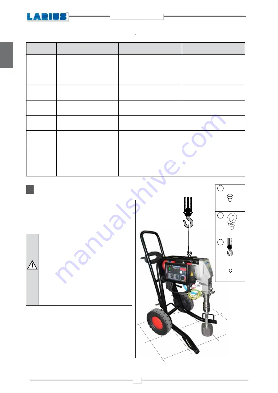
LIFTING POINTS

There are no precise lifting points for the machine in its entirety. In 
order to determine the most appropriate lifting points, refer to the 
geometric characteristics of the machine itself 

(proceed as shown)

The user is responsible for the operations of 
unloading and handling and should use the ma-
ximum care so as not to damage the individual 
parts or injure anyone.
To perform the unloading operation, use only 
qualified and trained personnel

 (truck and cra-

ne operators, etc.)

 and also suitable hoisting 

equipment for the weight of the installation or 
its parts. Follow carefully all the safety rules. 
The personnel must be equipped with the ne-
cessary safety clothing.

REMOVE THE SCREW

SCREW IN THE 

SUPPLIED EYEBOLT

LIFT THE MACHINE

1

2

3

Summary of Contents for Zeus

Page 1: ...Ed 005 11 12 ZEUS ZEUS OPERATING AND MAINTENANCE INSTRUCTION OPERATING AND MAINTENANCE INSTRUCTION ENGLISH P A I N T S P R A Y I N G E Q U I P M E N T...

Page 2: ...manual without prior notice This manual is to be considered as an English language translation of the original manual in Italian The manufacturer shall bear no responsibility for any damages or inconv...

Page 3: ...gun p 10 Check on power supply p 10 Connection of the tooling to the power supply p 12 Washing of the new equipment p 12 Preparing the product p 13 WORKING p 14 Start of the working operations p 14 Sp...

Page 4: ...tes wound and finger squashing risk due to movable parts in the equipment Tenersi lontano dalle parti in movimento Do not use the equipment without the proper protection Before any inspection or maint...

Page 5: ...p outlet and then sent to the gun through the flexible hose An electronic device located next to the reduction box is used to regulateandcontrolthepressureofthematerialleavingthepump When the pump rea...

Page 6: ...e phase RUN GENERATOR SUPPLY single phase MOTOR POWER MAX WORKING PRESSURE MAX DELIVERY MATERIAL OUTLET WEIGHT LEVEL OF THE SOUND PRESSURE MINIMUM WIDTH MINIMUM HEIGHT MAXIMUM HEIGHT MINIMUM ENCUMBRAN...

Page 7: ...DESCRIPTION OFTHE EQUIPMENT Electric motor Pressure transmitter Pumping group High pressure flexible pipe of compen sation 3 8 Description Recirculation tube Recirculation safety valve Line filter opt...

Page 8: ...12 13 14 15 Suction filter Pressure gauge Airless manual gun AT 300 Trigger safety clamp Description Earth cable with clamp Control equipment ON OFF switch Flexible pipe connection Description POS PO...

Page 9: ...chinehastobeswitchedoffandonagainusing switch 1 Eachtimethemachineisswitchedoff theconden sers remain charged for about 5 minutes Toavoidriskofshock whenremovingtheelectrical box wait until the conden...

Page 10: ...e machine is earthed Replace it Wait until the equipment has stopped completely before using it for a new job Solution TRANSPORT AND UNPACKING The packed parts should be handled as indicated in the sy...

Page 11: ...n the hose can create static electricity through discharges andsparks Itissuggestedtoearththeequipment The pump is earthed through the earth cable of the supply The gun is earthed through the high pre...

Page 12: ...F HEARING IN CASE OF WORK NEAR THE PLANT Never attempt to tamper with the calibre of in struments SETTING UP CONNECTION OFTHE FLEXIBLE HOSETOTHE GUN Connect the high pressure flexible hose F1 to the p...

Page 13: ...be means of a specific clamp F4 in order to protect the operator against any risk of static or electric shock Should anyone use an extension cable between the tooling and the socket it must have the...

Page 14: ...ositio ned correctly in order to earth the pump unit in the equipment properly Ensure the gun F3 is without nozzle Check the switch F5 is on the OFF 0 position before connecting the cable to the mains...

Page 15: ...the pump in order to avoid the contact between the solvent fumes and the electric motor For disposing of the washing liquid see the re quirements laid down in the Standards in force in the country in...

Page 16: ...ORDENSEPRODUCTS Never use products containing halogen hydrocarbons as methy lene chloride If these products come into contact with aluminium partsoftheequipment canprovokedangerouschemicalreactions wi...

Page 17: ...the recirculation safety valve G2 Make sure that the product circulates regularly from the circulation hose G5 Close the recirculation safety valve G2 Themachinecontinuestosuckupproductuntilithasfill...

Page 18: ...g at the maximum pres sure available releasing the gun trigger sudden increases of pressure can occur In this case the safety valve G5 opens automatically eliminating partoftheproductfromtherecirculat...

Page 19: ...Hold the spray gun trigger down Open the recirculation safety valve H3 to release the pressure in the circuit Lift the suction hose and replace the bucket containing the product with a bucket of clean...

Page 20: ...surfacesthatwillinsulate the container from the earth Hold the spray gun against the edge of the metal contained H5 Makesurethatthemachinesucksincleanwashing liquid Allow the cleaning liquid to discha...

Page 21: ...ore using again the equipment Take the cleaning liquid and store it in suitable containers Makesurethatthemachinesucksincleanwashing liquid Allow the cleaning liquid to discharge into anothercontainer...

Page 22: ...Open the circulation safety valve H3 to discharge the pressure in the circuit Lift the suction hose and replace the bucket of product with an empty bucket H6 Connect a rubber hose H7 to a water tap H...

Page 23: ...bber hose H7 and take away the bucket of water H6 Now point the spray gun H4 into the container H5 and press the trigger to recover any cleaning liquid left Run the pump s washing cycle until clean wa...

Page 24: ...ours with the pressure at 0 bar check that it is tightened all the way The supplied pin I3 ref 20144 also serves the purpose of closing and opening the pump unit s locking ring nut I4 This ring nut mu...

Page 25: ...control box clean in order to guarantee correct heat exchange with the ambient air We suggest cleaning using a jet of compressed air Pressure switch seal check Check that no material is escaping from...

Page 26: ...of the gun butt is too fine The nozzle is worn The gaskets of the pumping group are worn Suction or delivery valve dirty Drain valve defective Material leaking from the O Ring Check the correct conne...

Page 27: ...rt the gun clamp K4 Clamp inserted Clamp released Makesurethattheelectricalsystemisearthedand complies with regulations WARNING If the equipment is still under pressure after performing the operations...

Page 28: ...before going on with the operations follow the correct procedure of decompression The gaskets are self adjusting If a leak occurs they must be replaced Disconnect the product feed hose L1 from the pum...

Page 29: ...TENANCE Replacement of upper and lower gaskets 20 minutes Lock the pump unit into a vice and unscrew it with a 50mm wrench Release the pump unit from the body of the suction valve Grip the stem valve...

Page 30: ...Ring L19 and replace it making sure it is aligned correctly as illustrated Use a screwdriver to remove the two open ring guide bands L15 and replace them Use a size 24 spanner to unscrew the lower st...

Page 31: ...band L24 located below the seal L23 and insert a new band in the same position The positioning of the seal L23 equires special care during assembly Assistinsertionbyapplyingleveragetotheoutsideoftheri...

Page 32: ...eal L30 and replace it with a new one RemovetheOR L25 L26 L28 fromthebodyofthefootvalve L29 and from the ball seat holder L27 and if necessary replace them Reassemblethecomponentsintheirproperorder as...

Page 33: ...sh Insert the sleeve L31 into the lower pump unit L32 Screw on the complete foot valve L29 with the sleeve as sembly L30 Inordertoguaranteeaproperseal tightenthefoot valve L29 fully using a 50 mm span...

Page 34: ...ump casing all the way and if the delivery pipe is not correctly aligned unscrew the pump casing until the connectionisinthecorrectpositionbeforetighteningbyusing the ring nut N35 and the pin N36 supp...

Page 35: ...RE PARTS Electric motor Page 43 Electrical control exploded view Page 40 Carriage page 42 Basic hydraulic block ref 30400 Page 36 Complete electro mechanical Unit Page 34 Complete standard pumping ele...

Page 36: ...r ref 20213 Earth cable ref 5010 43 31 4 3 9 13 26 41 32 Material supplied not installed on the machine 17 16 18 15 21 36 42 1 38 14 19 17 22 33 25 44 24 39 6 5 23 23 8 7 30 28 27 34 35 40 45 29 37 4...

Page 37: ...32 33 34 35 36 37 38 39 40 41 42 43 44 45 INA Roller bearing Complete connecting rod Positioning spring Pump unit pivot Centring pin 6X20 Guide bushing Scraper Screw M4X10 Inspection hatch Tin plate d...

Page 38: ...15 14 22 36 37 38 38 39 40 30 53 54 55 56 57 58 58 59 60 61 62 63 23 64 24 9 34 34 25 61 26 28 27 31 32 65 66 68 67 69 41 English N BASIC HYDRAULIC BLOCK REF 35160 WARNING Always indicate code and qu...

Page 39: ...70 Discharge tube assembly Rubber holder 3 8 Bushing tube Pipe compensator 3 8 Union o tuboeGj 3 8 Recirculation valve compl OR 2087 Valve casing OR 2025 O Ring Complete rod Spring Bush Dowel M5X6 Pos...

Page 40: ...nd quantity for each part required 27 26 25 40 24 23 22 LIP 38 Tightening pin Ref 20144 CORRECT FITTING 21 20 19 CORRECT FITTING 18 11 41 15 14 13 12 10 42 17 16 37 Complete intake tube and recirculat...

Page 41: ...Sleeve Seal Adapter 3 8 AP M M Pump unit casing 67806 X0220 56Z EAR 148856 02 67806 X0220 A22Z Tightening ring nut Stuffing nut OR 3087 Accommodation ball seat See ball Elbow joint F F Gj 3 4 Suctionf...

Page 42: ...40 English O P ELECTRICAL CONTROL EXPLODED VIEW WARNING Always indicate code and quantity for each part required Complete 220V 50Hz box Ref 20350 110V 60Hz Ref 20350 110 14 8 5 6 3 12 6 7 2 4 13 1 9 1...

Page 43: ...18483 18493 20352 8011 34009 34008 20340 20349 30280 Electronic box A C Model 220V 50Hz Model 110V 60Hz Switch Panel Electronic box Screw Electronic board Short rubber seal Code Description Q ty Code...

Page 44: ...30304 3 2 4 5 7 6 8 1 WARNING Always indicate code and quantity for each part required Carriage in extended position Carriage in compact position CARRIAGE Complete carriage Carrying handle Pipe cap Bu...

Page 45: ...l components at least every 200 working hours The length of the brush contact must be higher than 9 mm to guarantee a good working of the rotary group Length of new brush Minimum length of the brush R...

Page 46: ...RS Code 11039 Green 30M Code 11038 White 60M Code 11037 Yellow 100M Code 11019 Red 200M HIGH PRESSURE HOSE 3 8 M16x1 5 max pressure 425 bar Code 18063 7 5 mt Code 18064 10 mt Code 18065 15 mt ANTISTAT...

Page 47: ...0 SFC27 60 SFC27 80 SFC29 20 SFC29 40 SFC29 60 SFC29 80 SFC31 40 SFC31 60 SFC31 80 SFC33 40 SFC33 60 SFC33 80 SFC39 40 SFC39 60 SFC39 80 SFC43 40 SFC43 60 SFC43 80 SFC51 40 SFC51 60 SFC51 80 Code 1827...

Page 48: ...cm 180 16 x 1 5 base SFC PLA 450 bar cm 130 1 4 base SFC PLA 450 bar cm 130 16 x 1 5 base SFC Code K11446 Code K11445 Code K11441 Code K11440 Code K11436 Code K11435 Art 16780 TELESCOPIC PAINT ROLLER...

Page 49: ...English PAINT SPRAYING EQUIPMENT L innovazione Quella vera...

Page 50: ...iaAntonioStoppani 21 Tel 39 0341 62 11 52 Fax 39 0341 62 12 43 E mail larius larius com Internet http www larius com NEW EXCALIBUR on carriage Rif 18776 NEW EXCALIBUR top finish Rif 18783 ELECTRIC PIS...

Reviews: