LT-1000 User & Installation Manual
Connecting
Lars Thrane A/S
www.thrane.eu
21 of 42
DIP-switch and LEDs
The LT-1000 NRU has a built-in DIP-switch, which is accessible from the bottom side of the unit, before the
pole or roof mount is mounted. To access the DIP-switch, the cap plug has to be removed; hereafter the
installer will have direct access to configuration of the DIP-switch. Furthermore, two LEDs are available on
the bottom side of the LT-1000 NRU. The placement of the DIP-switch and LEDs are illustrated in Figure 30.
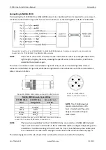
The configuration of the DIP-switch is illustrated in Figure 31.
IMPORTANT: The DIP-switch is configured to 4.800 baud (NMEA 0183) and ‘Open’ (NMEA 2000) when
leaving the factory. However, the installer should always check the settings of the DIP-switch
prior to an installation. Make sure to hold the LT-1000 NRU as illustrated on Figure 30, when
reading and configuring the DIP-switch, to avoid wrong settings.
The color code and description of the LEDs are illustrated in Table 4.
F
IGURE
30:
LT-1000
NRU
DIP-
SWITCH AND
LED
S
(
BOTTEM SIDE OF
LT-1000
NRU).
F
IGURE
31:
DIP-
SWITCH CONFIGURATION
(NMEA
0183
BAUD RATE AND
NMEA
2000
O
PEN OR
T
ERMINATED
)
LT-1000 NRU LEDs Color Description
Green LED
Red LED
Description
On
Off
Power on unit. Unit is ready for navigation.
On
On
Power on Unit. Error or warnings present. Check installation setup and
Troubleshooting on page 33 to resolve the problem. Connect the LT-
Service Tool to read-out details from the LT-1000 NRU, see Connecting LT-
Service Tool on page 25.
Off
NA
No power on unit.
T
ABLE
4:
LT-1000
NRU
LED
C
OLOR
C
ODE AND
D
ESCRIPTION
Summary of Contents for LT-1000 NRU
Page 2: ......


