The Chain Port is configured for the following communication parameters:
•
9600 baud.
•
8 data bits.
•
1 stop bit.
•
No parity.
To interconnect Access-T units via the Chain Port, perform the following steps:
1.
Remove the two-slot black Molex plug from the Chain Port connector
on the Access-T rear panel. (Contact Larscom if this plug has been lost.)
2.
Provide the required lengths of wire, preferably #22 or #24 AWG
braided wire.
3.
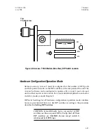
Connect the wires to the Molex plugs of all chained Access-Ts so that
all pin 1’s are wired to each other and all pin 2’s are wired to each
other, as shown in Figure 3-11. (If an Access-T is at the end of a chain,
it will have one wire in each slot; otherwise, it will have two wires in
each slot.) To make a wiring connection to a Molex plug:
a.
Turn the screw corresponding to the desired wire slot (1 or 2)
counterclockwise until the slot is open enough to accept the wire(s).
b.
Insert the wire(s) into the slot.
c.
Turn the screw clockwise until the wire(s) are held firmly.
4.
Insert the Molex plugs into the Chain Port connector.
Disconnecting a properly-wired Molex plug from an Access-T will not affect
communications between other units on the chain.
Chain Port Expander (RS485 to RS232)
The Larscom CP01 Chain Port Expander provides an interface between an
RS232 device and the RS485 Chain Port. Applications and installation of the CP01
are described in Appendix C.
External (Station) Clock
If a station clock is to be used as the reference clock, connect the clock cable to
the
EXT CLOCK
female BNC connector on the rear panel of Access-T.
Note:
The
EXT CLOCK
input employs TTL logic levels and has
an impedance of 50 ohms.
Chapter 3
ACST-0351-005
Installation
June 1996
3-20


