
EXP-MTSTR-DOL-3P-480V-5HP-5A
Explosion Proof Combination Motor Starter
Class I, II, III - 5HP, 480V Rated 3PH - NEMA 4, 4X
Instruction Manual
Thank you for your purchase of the Larson Electronics EXP-MTSTR-DOL-3P-480V-5HP-5A combo motor starter.
WARNING
TO AVOID THE RISK OF FIRE, EXPLOSION OR ELECTRIC SHOCK, THIS PRODUCT SHOULD BE INSTALLED,
INSPECTED AND MAINTAINED BY A QUALIFIED ELECTRICIAN ONLY, IN ACCORDANCE WITH ALL
APPLICABLE ELECTRICAL CODES.
TO AVOID ELECTRIC SHOCK:
•
BE CERTAIN ELECTRICAL POWER IS OFF BEFORE AND DURING INSTALLATION AND MAINTENANCE.
•
PRODUCT MUST BE CONNECTED TO A WIRING SYSTEM WITH AN EQUIPMENT-GROUNDING
CONDUCTOR.
TO AVOID EXPLOSION:
•
MAKE SURE THE SUPPLY VOLTAGE IS WITHIN THE VOLTAGE RATING.
•
ENSURE THE MARKED T RATING IS LESS THAN THE IGNITION TEMPERATURE OF THE HAZARDOUS
ATMOSPHERE.
•
DO NOT OPERATE IN AMBIENT TEMPERATURES ABOVE THOSE INDICATED ON THE PRODUCT
NAMEPLATE.
•
DO NOT OPERATE IF THE LENS, CORD, SEALS, HOUSING, RECEPTACLES, ETC. IS CRACKED OR
DAMAGED. IF SO, DISCONTINUE USE AND CONTACT MANUFACTURER FOR REPLACEMENT PARTS.
•
ALL FASTENERS SHOULD BE PROPERLY SEATED.
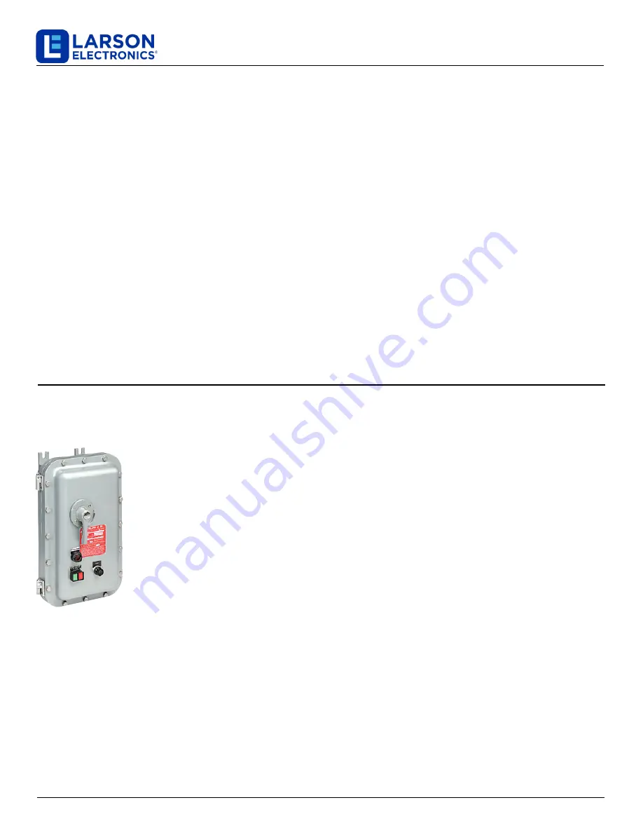
The Larson Electronics EXP-MTSTR-DOL-3P-480V-5HP-5A Explosion Proof Combination Starter provides motor starting
solutions for industrial equipment located in combustible environments. This 5 HP unit provides compatibility with 480V
three-phase and is protected by a NEMA 4, 4X enclosure. The solid-state, explosion proof device features manual and
automatic reset controls.
MOUNTING
We recommend only a licensed electrician complete the installation of this unit.
All applicable
local and national electrical and building codes should be followed when installing. Consult
your local authority for interpretation of codes if necessary. Unit is heavy and may require 2 or
more people to lift and hold while mounting.
The Larson Electronics EXP-MTSTR-DOL-3P-480V-5HP-5A Explosion Proof Combination Starter is
designed for surface mounting applications, facilitated by slotted mounting feet on the rear of the
enclosure. The enclosure can be mounted to any flat surface capable of supporting the load. Lift the
enclosure into place and drive heavy duty mounting screws or bolts through the mounting slots and
surface. Be sure enclosure is mounted securely and that surface is sturdy enough to support the load.
WIRING
We recommend only a licensed electrician complete the installation of this unit. Check product label for correct
voltage ratings!
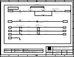
Refer to wiring diagram included with the starter unit if needed.
Supply power should always be
off when enclosure is open within the hazardous area.
Line-in
voltage of
480vAC
is fed through the top hub of the enclosure, and connected to the main breaker switch via the top
terminals.
Line-in voltage of
480vAC
is then routed through the
contactor
and out the bottom hub of the enclosure to be
connected to equipment.
The
coil of the contactor and the remote reset module
runs on
120v
AC
separately from the main
circuit breaker
and the contacts of the contactor
, and thus must also be supplied by it's own wiring.
The
contactor overload
will automatically cut power to the equipment in the event of a circuit overload to protect the equipment from damage.
The
main breaker will also trip i
n the event of an overcurrent or short circuit
.
Two plugged hubs are available on the front of the
enclosure for optional installation of control operators or indicators, such as pilot lights or push buttons.
Refer to the wiring
diagram included with the unit for specific wiring connections.
Abide by all applicable local and national electrical
and building codes for the hazardous area when installing. Consult your local authority for interpretation of codes
if necessary.
Be sure unit is properly grounded using the supplied ground wire.
Larson Electronics, LLC
Phone: (877) 348-9680
Fax: (903) 498-3364
www.larsonelectronics.com
1
of
2


