3
INSTRUCTION MANUAL
Bench Press with Air Pump
2. TECHNICAL FEATURES.
CYLINDER
MODEL KC01113
KC02013
•
Max. Pushing Capacity (Tn.)
10 Tn
20 Tn
•
Working max. pressure (Kg/cm
²
)
700 Kg/cm
²
700
Kg/cm
²
•
Stroke (mm.)
130 mm.
130 mm.
•
Oil capacity (cc)
214,7 cc
431.37 cc
•
Area (cm²)
15,9 cm²
33,18 cm²
•
Free advance speed (mm/sg)
1.7 mm/sg
0.9 mm/sg
•
Max. Pressure advance speed
1.7 mm/sg
0.9 mm/sg
AIR PUMP
MODEL Z12107
Z12107
•
Tank capacity (cc)
2100 cc
2100 cc
•
Working pressure (Kg/cm
²
)
700 Kg/cm
²
700
Kg/cm
²
•
Weight (Kg)
4,6 Kg.
4,6 Kg.
WELDED-MECHANIZED FRAME
MODEL
ECZ01113
ECZ02013
•
Working height (mm.)
352 mm.
330 mm.
•
Working Width (mm.)
350 mm.
500 mm.
•
Total weight of the machine (Kg.)
42 Kg.
90 Kg.
3. ESSENTIAL SAFETY REQUIREMENTS.
3.1
GENERAL CONDITIONS.
DANGEROUS AREA
The speed of the hydraulic cylinder during its extension is less than 30 mm/second. Therefore then machine should be considered by the application of ANNEX V of
the Declaration of CE Conformity.
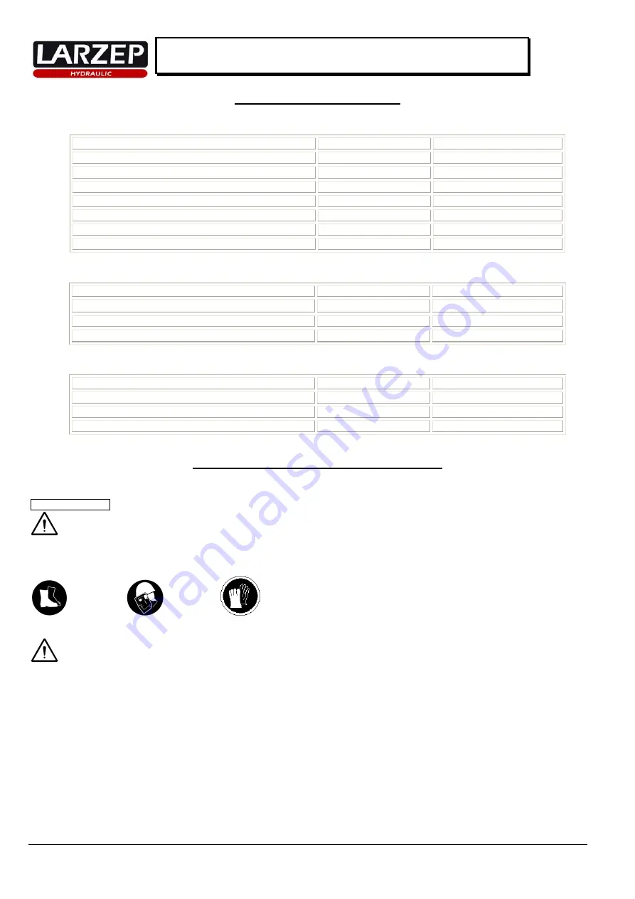
Operators standing in the dangerous area around the machine should protect their feet, faces and hands from metal pieces being ejected during pressing.
Feet protection
Face protection
Hands protection
Used materials and components are not for the health and safety of operators. The hand pump contains LARZEP hydraulic oil ISO: HV46.
3.2 COMANDS
The cylinder advances when we drove the pedal of the air pump.
The pump’s pedal has three positions: advance (“pump”), retroacting (Release) and it maintains the pressure loosen the pedal.
In order to start the equipments it is necessary to connect the pump to the compressed air connection at 6 Bar pressure.
In order to stop the cylinders advance, release the pedal or disconnect the compressed air feeding. For a new beginning it will be necessary to unblock the device and
push the pedal in “pump” position.
3.3 SAFETY PREVENTIVE ACTIONS AGAINST MECHANICAL RISKS
The construction of machine has been calculated to bear without any breaking under conditions of foreseen utilization and for the whole life of the machine. The
hydraulic components have been designed and calculated in compliance with the ANSI B30.1, and have been proved to 875Kg./cm
²
of pressing.
The frame of the machine does not cause to be dangerous in that sense.
The hydraulic pump is equipped with an internal security valve in the tank, out of operator’s control and rated at 700 Kg./ cm
²
. The hydraulic cylinder is also furnisher
with a pressure relief valve, rated at 700 Kg./ cm
²
, which prevents the retraction chamber of the cylinder from overpressures in case of obstruction of the return way.
Due to the
FUNCTIONAL REASONS
it is considered to be the space between the columns, the bed and the hydraulic cylinder piston.
Due to the
MATERIAL PRESSED
it is supposed to be surrounding area to the machine in case of metal parts being ejected during pressing.
HIDRAULIC OIL IS TOXIC IF IT ENTERS THE BLOODS STREAM. NEVER PLACE A FINGER OVER ANY ORIFICE OR LEAK, WHICH
COULD BE PRESSURIZED, SUCH AS THE HYDRAULIC LINE, AS THIS COULD CAUSE OIL TO BE INJECTED INTO BLOOD STREAM.


