background image

7

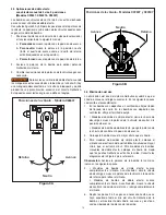
Figure 4

4.7    Pressure Relief Valve

All pumps contain a factory set relief valve to prevent 

over-pressurization. Do not attempt to readjust, disable or 

modify this valve.

5.0    MAINTENANCE

5.1    Hydraulic Reservoir

Check oil level regularly. Drain oil and refill with Larzep 

hydraulic oil (Part No. AZ8901) every 12 months. If pump 

is used in dirty environments, change the oil more often.
Use only genuine Larzep hydraulic oil or a comparable 

high quality ISO 32 hydraulic oil having the same technical 

characteristics.
The use of any other fluid could damage the seals or 

equipment and will make the product warranty null and 

void.

5.2  Filling Non-Vented Reservoirs 

(all models EXCEPT W26507 and X26507) 
Important:

 Non-vented reservoirs have a predetermined 

oil level that should not be exceeded. Refer to table 

Section 2.0 for oil capacities. Never fill a pump beyond 

the maximum oil level or capacity recommended by the 

manufacturer.

•  Non-vented hand pumps always require some air in 

the reservoir to function properly.

•  A non-vented reservoir should never be completely 

filled. If a non-vented reservoir is completely filled, 

a vacuum will form, preventing proper operation of 

the pump.

5.3  Filling Vented Reservoirs 

(models W24507, X24507, W26507 and X26507) 

•  Vented reservoirs can be filled up to the bottom 

of the oil fill hole. However, it is recommended to 

leave a small air gap to allow optimum functioning 

of the venting system.

•  Models W26507 and X26507 must be filled to 

within 25 mm of the top plate.

5.4    Adding Oil to the Pump

  WARNING  

Always add oil with cylinders fully retracted 

(extended if pull cylinders) or the system will contain more 

oil than the reservoir can hold.

Add oil as described in the following steps:
1.  Remove oil fill plug from reservoir.
2.  Determine if your pump has a vented or non-vented 

reservoir. Refer to Table 2 earlier in this manual.

3.  Add oil to the reservoir as required. Refer to oil fill 

information in Sections 5.2 and 5.3 (as applicable).

4.  Reinstall oil fill plug after adding oil.
5.  Remove air from system if necessary, as described in 

Section 4.6.

6.  Recheck oil level after removing air.

5.5    Keeping Oil Lines Clean

When coupler halves are disconnected, always install 

dust caps. Use every precaution to guard unit against the 

entrance of dirt, because foreign matter may cause pump, 

cylinder, or valve failure.

Summary of Contents for W Series

Page 1: ...t to LARZEP S A or the authorized dealer which sold you the hydraulic equipment LARZEP S A will repair or replace the faulty equipment whichever is deemed most appropriate LARZEP S A shall not be held liable for any consequential damages or losses which may occur as a result of faulty equipment RECEIVING INSTRUCTIONS Important Make sure to inspect all of the components for shipping damage If damag...

Page 2: ...anical load holding Cylinders without these features should never be used as a load holding device After the load has been raised or lowered it must always be blocked mechanically WARNING USE ONLY RIGID PIECES TO HOLD LOADS Carefully select steel or wood blocks that are capable of supporting the load Never use a hydraulic cylinder as a shim or spacer in any lifting or pressing application WARNING ...

Page 3: ... 46 0 4 0 2600 14 5 W24507 2 28 700 46 0 4 0 4450 18 1 X24507 2 28 700 46 0 4 0 4450 19 5 W26507 2 28 700 126 0 4 9 6500 20 0 X26507 2 28 700 126 0 4 9 6500 20 8 Note Models beginning with W are for use with single acting cylinders and tools Models beginning with X are for use with double acting cylinders and tools 2 2 Hand Pump Hydraulic Connections Outlet Port Outlet Ports Release Screw Assembly...

Page 4: ...retract port b For double acting cylinders use two hoses Connect the first hose from the pump advance port A to the cylinder advance port Connect the second hose from the pump retract port B to the cylinder retract port WARNING One or more shipping plugs are used to prevent residual oil from leaking out of port s during shipment Do not operate pump with the shipping plug s installed Oil may be exp...

Page 5: ...7 W20307 W20807 W21807 W22607 and W24507 1 Close release valve by turning clockwise as shown in Figure 1 Figure 1 CAUTION Close release valve HAND TIGHT ONLY Using tools on release valve can damage it and cause the pump to malfunction 2 Operate pump handle to deliver hydraulic power to system Pressure will be maintained until release valve is opened 3 Open release valve turn counter clockwise to r...

Page 6: ...oval Removing air from the hydraulic system will help the cylinder to advance and retract smoothly Refer to the procedure in the following steps 1 On pumps with non vented reservoirs loosen the oil fill plug On pumps with vented reservoirs loosen the vent screw 2 Single acting pump models Close the release valve or move the control valve lever to the advance position Double acting pump models Move...

Page 7: ...illed If a non vented reservoir is completely filled a vacuum will form preventing proper operation of the pump 5 3 Filling Vented Reservoirs models W24507 X24507 W26507 and X26507 Vented reservoirs can be filled up to the bottom of the oil fill hole However it is recommended to leave a small air gap to allow optimum functioning of the venting system Models W26507 and X26507 must be filled to with...

Page 8: ...ording to the maintenance instructions Close the release valve Check that all couplers are fully tightened Do not attempt to lift more than rated tonnage Remove air according to instructions Check for damage to cylinder Have cylinder serviced by a qualified hydraulic technician Cylinder advances but does not hold pressure Leaking connection Leaking seals Internal leakage in pump Check that all con...

Page 9: ... S A o al distribuidor autorizado que le vendió el equipo LARZEP S A reparará o reemplazará el equipo defectuoso según se juzgue oportuno LARZEP S A no será responsable de ninguna pérdida o daño que pueda ocurrir como resultado de un equipo defectuoso INSTRUCCIONES DE RECEPCIÓN Importante Asegúrese de inspeccionar todos los componentes para comprobar si están dañados a causa del transporte Si encu...

Page 10: ...cánica de la carga Cilindros sin estas características nunca deberían usarse como un dispositivo de retención de cargas Después de que la carga se haya subido o bajado debe bloquearse siempre mecánicamente ADVERTENCIA USE SOLO PIEZAS RÍGIDAS PARA SOSTENER CARGAS Seleccione cuidadosamente bloques de acero o de madera capaces de soportar la carga Nunca use un cilindro hidráulico como calza o separad...

Page 11: ... 46 0 4 0 4450 18 1 X24507 2 28 700 46 0 4 0 4450 19 5 W26507 2 28 700 126 0 4 9 6500 20 0 X26507 2 28 700 126 0 4 9 6500 20 8 Observación Los modelos que comienzan con W son para uso con cilindros y herramientas de simple efecto Los modelos que comienzan con X son para uso con cilindros y herramientas de doble efecto 2 2 Conexiones hidráulicas de la bomba manual Puerto de salida Puertos de salida...

Page 12: ...ntilación o sin ventilación Consulte la tabla siguiente para determinar el tipo de depósito en la bomba 3 3 Purgar el depósito modelos W24507 X24507 W26507 y X26507 Para que pueda funcionar la bomba debe abrirse la ventilación Si la ventilación está bloqueado o cerrado la bomba no funcionará correctamente o no será operativa Gire el tornillo de purga en sentido antihorario para abrir ventilación P...

Page 13: ...W21807 W22607 y W24507 1 Cierre la válvula de descarga girándola en el sentido horario como se muestra en la Figura 1 Figura 1 PRECAUCIÓN Cierre la válvula de descarga SÓLO A MANO El uso de herramientas en la válvula de descarga pueden dañarla y provocar un mal funcionamiento de la bomba 2 Accione la palanca de la bomba para aplicar potencia hidráulica al sistema La presión se mantendrá hasta que ...

Page 14: ...ire del sistema hidráulico ayudará a que el cilindro avance se retraiga suavemente En los siguientes pasos se describe el procedimiento 1 En las bombas con depósitos sin ventilación afloje el tapón de llenado de aceite En las bombas con depósitos con ventilación afloje el tornillo de purga 2 Modelos de bomba de simple efecto cierre la válvula de descarga o mueva la palanca de la válvula de control...

Page 15: ...ma un vacío impidiendo el funcionamiento correcto de la bomba 5 3 Llenar depósitos con ventilación modelos W24507 X24507 W26507 y X26507 Los depósitos con ventilación pueden llenarse hasta la parte inferior del orificio de llenado de aceite Sin embargo es recomendable dejar un pequeño espacio de aire para permitir un funcionamiento óptimo del sistema de purga Los modelos W26507 y X26507 debe llena...

Page 16: ... de descarga Compruebe que todos los enchufes estén completamente apretados No intente levantar más tonelaje del nominal Elimine el aire según las instrucciones Compruebe daños en el cilindro Haga revisar el cilindro por un técnico hidráulico cualificado El cilindro avanza pero no retiene la presión Conexión con fugas Fugas en las juntas Fugas internas en la bomba Asegúrese de que las conexiones e...

Reviews: