background image

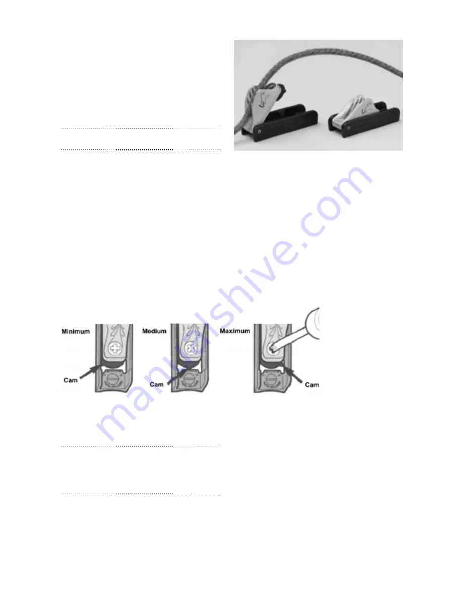
When adjusting the kick-up cleat mechanism on 
your Pico rudder, we strongly recommend that 
you set the cam at the minimum setting and 
progressively increase it to suit your experience and 
style of sailing.
If racing and sailing in strong winds you will want 
to set the kick –up load higher. If recreational 
sailing off the beach you will want to set the kick 
up much lower.

Warning:

 Running aground with the kick-up set incorrectly 

could damage your rudder and the hull.

The auto-release cleat provides the neatest and 
best solution to the problem of how to lock-down 
a rudder blade yet allow it to flip up if it hits 
the bottom or a solid obstacle in the water. The 
cleat holds ropes securely, yet will release them 
immediately when the cleat is overloaded. Once 
tripped, it can be easily reset in seconds by just 
pushing the cleat back down into its base. 
The cleat is also fitted with an adjustable cam so 
that the release tension can be set to suit the boat 
and local conditions. The cam is adjusted until the 
rudder blade is held down reliably under maximum 
sailing conditions. The cleat will then be set so that 
the least strain is put on the rudder if it hits an 
obstacle.

Setting the Release Load

1.    Test release load with “cam” at minimum 

setting.

2.    To increase load use a screwdriver to rotate 

“cam” towards maximum. 

Warning:

 To avoid damaging equipment, make small adjust-

ments and test each increase. Tests show that release loads of 
240kg (530lbs) are possible with the cam at “maximum” setting. 
Smaller or worn ropes release at higher loads than larger new 
ropes.

Summary of Contents for Pico

Page 1: ... and Cunningham 5 Raising the Mast 6 Rigging and Fitting the Boom 7 Rigging and Fitting the Vang 8 Traveler and Mainsheet 9 Rigging and Raising the Jib 10 Fitting the Rudder Assembly 11 Fitting the Daggerboard 12 Mainsail Reefing Stowing the Mainsail 13 Launching and Basic Safety On The Water 14 Care and Maintenance 15 Examination Report ...

Page 2: ...t sail Leech Rear edge of the sail Leeward The side of the boat on which the main sail is set when sailing Luff Forward edge of the sail Mast Main vertical spar supporting the rig sails Mainsheet The rope controlling the position of the mainsail Mast Step Integral tube where the mast heel foot of the mast is located Port The left hand side of the craft looking forward Outhaul Purchase system for t...

Page 3: ... Pico comes in the following main component parts 1 Pico Hull 2 Pico Sail Kit Jib and mainsail 3 Pico Spar Kit Upper lower mast and boom 4 Pico Foil Kit Dagger board rudder assembly blocks fittings and Rope Pack 5 Pico Document Pack Rigging and owners manuals sail numbers and CE certificate 1 2 3 4 5 ...

Page 4: ...lyard Pre s Blue 4mm x 5m 7 Outhaul control line Pre s Blue 4mm x 3 65m 8 Cunningham control line Pre s Yellow 4mm x 1 25m 9 Jib sheet Yellow 7mm x 6m 10 Mainsheet Blue 7mm x 10m Pico Blocks and Fittings Supplied as part of foil kit 1 Vang lower block inc hook x1 2 Vang upper blocks x2 3 Large traveller block inc sister clip x1 4 Small traveller block inc sister clip x1 5 Twisted hook for clew out...

Page 5: ...pecs pico length ft m 11 48 3 50 beam ft m 4 69 1 43 draft ft m 2 90 0 88 mainsail area ft m 55 33 5 14 jib area ft m 11 73 1 09 hull weight lb kg 154 32 70 00 capacity skill level race level optimal weight lb kg 132 176 60 80 transport specs pico race mainsail area ft m 68 14 6 33 beginner advanced club 1 3 people trailer or cartoppable ...

Page 6: ...ay the sail on a flat surface port side up 2 The numbers on the starboard side are always higher than the port side 3 Measure 25 mm above the P of the Pico screen print and draw the base line perpendicular to the leach and blue sail panel 4 Measure 70 mm from the leach and draw a line parallel to the leach and perpendicular to the base line previously drawn 5 Position the port sail numbers startin...

Page 7: ... the sail numbers 60 mm apart as above 1 Insert the upper mast into the lower mast making sure that the red arrows align 2 Thread the jib halyard through the halyard plate eye on the upper mast 3 Take one end of the halyard and pass it through the halyard cleat on the port side of the lower mast before temporarily tying the 2 free ends together 4 Unfold the mainsail try to keep it clean and dry an...

Page 8: ...the D ring before feeding it back though the cleat tying a bowline loop handle in its end 13 Tighten the cunningham line just enough to remove any wrinkles in the luff of the mainsail before finally securing it in the cleat 8 9 5 Raising The Mast WARNING In windy or bad weather the boom can be rigged before raising the mast and without clipping it onto the mast WARNING The mast is metal and is an ...

Page 9: ...d through one of the sister clips loose kit part before tying a Figure 8 stopper knot in its end 6 Take the long piece of shock cord and tie one end through another one of the sister clips loose kit part before tying a Figure 8 stopper knot in its end 7 Clip the two aforementioned sister clips together to form the tidy up line for your clew outhaul 8 Take the shock cords remaining loose end and ti...

Page 10: ... the longer secondary vang line and attach one end directly through the central hole Not around the pulley sheave of the second upper vang block using a bowline 6 Fead the remaining loose end around the purchase system as shown before passing it through the cleat of the vang lower block tying a 30 cm diameter loop handle in its end 7 Tension the vang to the desired amount and secure it in the clea...

Page 11: ...end through the remaining mainsheet block positioned on the lower mid section of the boom travelling in a stern to bow direction f Pass the loose end through the mainsheet ratchet block situated on the up stand turret in the middle of the boats cockpit Take care to ensure the mainsheet passes through the block such that the ratchet block free wheels when sheeting in but locks when sheeting out g F...

Page 12: ...ew hole with its corresponding recess hole on the uppermost aft rear surface of the rudder head tiller arm hood 3 Locate the tiller arm retaining screw driving it carefully through both the rudder head and the tiller arm 4 Clip the tiller extension to its mounting bracket on the uppermost forward surface of the tiller arm 5 Take the rudder assembly and pass the tiller extension and tiller arm unde...

Page 13: ...opes securely yet will release them immediately when the cleat is overloaded Once tripped it can be easily reset in seconds by just pushing the cleat back down into its base The cleat is also fitted with an adjustable cam so that the release tension can be set to suit the boat and local conditions The cam is adjusted until the rudder blade is held down reliably under maximum sailing conditions The...

Page 14: ...ng a capize the boat will invert and there is a risk of entrapment In strong winds or if you are unsure whether you can cope with the conditions it is always best to reef the sail down to reduce its area 1 Ease the vang and unhook the lower vang block from the eye bracket on the aft face of the mast immediately above deck level 2 Un cleat the outhaul control line 3 Rotate the mast through 720 degr...

Page 15: ...iling in a new area 7 Always check the condition of your craft before setting off 8 Check for overhead cables when rigging launching and recovering 9 The use of a LaserPerformance supplied Pico mast head float is highly advisable This device will assist in the prevention of complete inversion in the event of capsize Launching 1 Raise the rig with the boat facing into the wind 2 Launch the boat usi...

Page 16: ...ly designed for the product Hulls damaged through using an incorrectly designed or wrongly set up trailer or trolley are not covered under warranty When securing your boat to a trailer for transport be very careful that ratchet straps and ropes are not over tight ened and that there is sufficient padding under the strap or rope to prevent the hull deck from being damaged through abrasion or pressu...

Page 17: ...15 Examination Report ...

Page 18: ... any of their products as part of their continuous development program LaserPerformance north america PO Box 1409 Norwalk Connecticut 06856 USA CustomerCare LaserPerformance com LaserPerformance europe Station Works Long Buckby Northamptonshire NN6 7PF United Kingdom CustomerCare LaserPerformance com LaserPerformance international Unit A1 22nd floor MG Tower 133 Hoi Bun Road Kwun Tong Hong Kong Cu...

Reviews: