background image

I

N

-

SCOPE 

D

ISPLAY 

I

NTENSITY


Electronic Copy of LTI’s UltraLyte User’s Manual – 7

th

 Edition June 1998


36


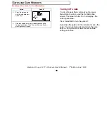
In-scope Display Intensity


The in-scope display has 22 intensity settings from 
off (0) to bright (21). You adjust the brightness with 
the 

br

 menu option. Use the procedure in the table 

at right. 

Each time you increase the brightness index by 1, 
the in-scope display doubles in intensity. The 
brightness setting displays in the scope as well as 
on the screen, to make getting the right setting easy. 


Action Result 

1. Press 

Menu/Options 

until the screen 
displays the 

br

 xx 

option (xx is the current 
setting). 

MENU


2. 

Press Test/Edit Up or 
Backlight/Edit Dn until 
the setting is correct. 

MENU


3. 

Return to speed or survey mode by pressing the 
appropriate button. Go to the next menu option by 
pressing Menu/Options. 


For Internal Use Only. Not for Distribution.

Summary of Contents for UltraLyte

Page 1: ...For Internal Use Only Not for Distribution...

Page 2: ...from accident disaster misuse abuse or non LTI modification of the product To activate your warranty return the warranty card from the front of this manual to LTI within 30 days of purchase To obtain...

Page 3: ...t be held responsible if any LTI authorized dealer has been advised of the possibility to such damages or for any claim by any other party Note The Warranty Validation Card at the front of this manual...

Page 4: ...a large number of options and is highly configurable This manual describes all the possible options Your particular UltraLyte instrument may not have all the options described The UltraLyte LR long r...

Page 5: ...mmended that you avoid staring into the transmit aperture while firing the laser The use of optical instruments with this product may increase eye hazard Never attempt to view the sun through the scop...

Page 6: ...eed measurement SPEED SPEED OPTIONS Time Over Distance SPEED TOD SPEED OPTIONS UL100 Distance Measurement Slope distance SURVEY SURVEY OPTIONS UL200 Distance Measurement Horizontal distance SURVEY SUR...

Page 7: ...IONS BACKLIGHT EDIT DN To select an option value or to turn an option on or off Test Functions Display test All display segments on TEST EDIT UP Aim test tone TEST tt Battery voltage TEST BATT Delta d...

Page 8: ...he Stock for Right handed Operation 9 Adjusting the Length and Angle 10 Refolding the Stock 10 ATTACHING THE YOKE 11 POWERING ON AND OFF 12 Testing the Display 12 Checking the Model Number 12 Restorin...

Page 9: ...ng Off a Gate 39 MEASUREMENT UNITS 40 Notes 40 CONTINUOUS MODE 41 MUTING THE INSTRUMENT 42 POWER CONSERVATION INTERVALS 43 SETTING DOWNLOAD FORMATS 44 TESTING DISPLAY INTEGRITY 45 SCOPE ALIGNMENT TEST...

Page 10: ...TIONS 58 APPENDIX A 59 SERIAL INTERFACE SPECIFICATIONS 61 Data Formats 61 Format Parameters 62 UltraLyte Download Format 62 Version Queries 62 Speed Range Data Message Format 63 Survey Data Message Fo...

Page 11: ...e to the instrument or if any ordered part is missing contact the shipper Basic UltraLyte Package UltraLyte instrument Two C batteries User s manual Padded carrying case Accessories In addition you ma...

Page 12: ...ances to target objects The UL200 in addition to measuring speed and range has a tilt sensor that measures inclination angles The tilt sensor allows the instrument to compute horizontal distance measu...

Page 13: ...s transmits infrared laser signals the bottom lens receives signals back from the target and feeds signal information to the internal circuitry The internal circuitry consists of a laser range sensor...

Page 14: ...rotated up through 180 degrees and down through 180 degrees The LCD Screen The LCD screen displays measurements and option indicators When the instrument is powered on for example the speed measureme...

Page 15: ...rmat or in the same format as earlier Laser Technology speed detection instruments for compatibility with existing software Sighting Scope Mounted atop the UltraLyte is a single power sighting scope T...

Page 16: ...fic survey measurement options front panel Speed Options Activates the instrument s speed measurement mode Selects specific speed measurement options Left front panel Select Edit Selects option values...

Page 17: ...strument handle Warning The UltraLyte is designed to accept normal C cells NiCad batteries can be used but they tend to vary in size Laser Technology will not be responsible for damage that results fr...

Page 18: ...ng the Stock Unfolding the Stock for Left handed Operation To open the stock for left handed operation 1 Loosen the stock by turning the tension knob counter clockwise 2 Rotate the stock 180 degrees 3...

Page 19: ...Hold the instrument firmly and press down on the retaining plate with sufficient force to disengage the plate from the stock s retainer peg 2 Pull the stock away from the body of the instrument and r...

Page 20: ...and move the stock up or down Usually it is best if the stock is at a slight downward angle Refolding the Stock To refold the stock extend it to its full length and reverse the procedure you used to...

Page 21: ...dapter to the instrument To attach the yoke adapter screw the mounting bracket and adapter into the mounting holes on the side of the instrument base Fit the yoke onto the mounting bracket and tighten...

Page 22: ...ee the illustration at left The instrument includes three simple functions you can perform at power on time Those functions are Testing the display Checking the model number and units Restoring factor...

Page 23: ...level of the instrument s internal software MPH and F indicate the factory default speed and range units in effect at the time the instrument was shipped Restoring the Default Configuration When the...

Page 24: ...s as the units the instrument is using for measurement and the mode the instrument is operating in When you first power on the instrument every indicator on the screen displays for a brief time You ca...

Page 25: ...peed units MPH Miles Per Hour KmH KiloMeters per Hour CmS CentiMeters per Second JAM Jam detection Indicates a jamming signal GS Gate Short Artificially restricts the minimum range of the instrument G...

Page 26: ...lable on the instrument DELTA Distance Difference Distance difference test mode See Instrument Confidence Check for details MUTE Mute silent mode The instrument indicator sounds have been turned off S...

Page 27: ...icts the maximum range of the instrument Measurement units F M MPH KmH CmS D G Sets the units to be used to take measurements Continuous mode CONT Alternate speed measurement mode in which the instrum...

Page 28: ...ingle high pitched tone The instrument succeeded in taking the intended measurement Single low pitched tone The instrument was unable to take the intended measurement due to an error An error code dis...

Page 29: ...Once in edit mode the instrument exhibits the following behavior Select Edit selects the next digit to the right If the right most digit is already selected exits edit mode and saves the current value...

Page 30: ...e aiming dot and projects it onto the scope face the second takes the measurement Or if you press and hold the trigger down the red dot will turn on and the instrument will begin a measurement about t...

Page 31: ...rred The speed calculated for the target displays in the LCD and in the scope If the target was going away from you when it was measured the speed displays as a negative number if the target was appro...

Page 32: ...toward or away from you the velocity measured by the UltraLyte is identical to the vehicle s true speed For safety however the instrument is usually set up on the side of the road resulting in an angl...

Page 33: ...far away that the angle between it and the instrument is very small indeed and the instrument s perception of the target s speed is identical to its true speed As the vehicle approaches however the a...

Page 34: ...9950 9987 200 0000 6000 9165 9798 9950 The diagonal created by the boldface numbers indicates the boundary between acceptable and unacceptable parameters Numbers above the diagonal are acceptable marg...

Page 35: ...of the UltraLyte to measure how long it takes the vehicle to travel that distance The basic procedure is this 1 Locate two suitable reference points 2 Enter the distance between the two points the re...

Page 36: ...d Options button right button panel to invoke TOD mode SPEED TOD F 3 Press and hold the Select Edit button to invoke edit mode SPEED TOD F Action Result 4 Edit in the distance For this example we use...

Page 37: ...spot that forms a straight line with your two reference points or as near to a straight line as you can manage and still see both points clearly Then measure both points The instrument calculates the...

Page 38: ...point and press the trigger The screen displays the distance SPEED TOD F 4 Press Select Edit to go to the second distance display SPEED TOD F Action Result 5 If you are measuring directly from one ref...

Page 39: ...the TOD screen If not press Speed Options to display it SPEED TOD F 2 Press Select Edit The measurement screen displays MPH SPEED TOD F 3 When a vehicle passes one point press the trigger to begin tim...

Page 40: ...asurement When you start the clock the instrument begins to tick so you know the clock is running The ticking noise continues until you stop the clock You may continually clock vehicles between the ch...

Page 41: ...clination vertical distance The UltraLyte 100 has no way to measure angles and takes only slope distance measurements The UltraLyte 200 however has a tilt sensor that allows it to measure inclination...

Page 42: ...ing dot and sight the target through the scope 3 Press the trigger SURVEY F You have just taken a distance measurement to your fence or whatever target you chose Each survey measurement operates in th...

Page 43: ...verything at once But suppose for example that an obstruction prevents you from taking a reliable reading with one sensor In that case you can use the Group feature and shoot a slope distance measurem...

Page 44: ...e form Exx where xx is an error code number Error codes display in the numeric display area In speed mode for example errors show at the top of the screen SPEED Measurement error conditions typically...

Page 45: ...3 Measurement error unstable targeting Caused by poor aiming or by panning off the target E04 TOD timing error The target was timed for less than 1 second Code Explanation E05 TOD time out The target...

Page 46: ...ightness index by 1 the in scope display doubles in intensity The brightness setting displays in the scope as well as on the screen to make getting the right setting easy Action Result 1 Press Menu Op...

Page 47: ...his range gate window Gating is useful when you must restrict your speed detection operations to a particular area or during a survey in which partial obstructions present a danger of giving false rea...

Page 48: ...feet 610 meters 3998 feet 1218 meters for the UltraLyte LR The maximum allowable value of the long gate is 2005 feet 612 meters 4003 feet 1220 meters for the UltraLyte LR Setting a Gate Value You can...

Page 49: ...enu option by pressing Menu Options Turning Off a Gate To turn off a gate that is currently set on press Menu Options until you get the first GS or GL screen The screen shows On and displays the curre...

Page 50: ...indicator to M or F MENU M Return to speed or survey mode by pressing the appropriate button Go to the next menu option by pressing Menu Options Select angle units in the UL200 in the same way press M...

Page 51: ...ng as you hold down the trigger Release the trigger and the instrument finishes its latest reading and stops If an error code is shown when you release the trigger the instrument will display either t...

Page 52: ...y noise from the instrument you can mute the instrument so it makes no noise When mute is on LAS appears in the scope to let you know that the laser is firing Next the in scope aiming dot disappears t...

Page 53: ...display shuts off In scope aiming dot 20 sec Aiming dot shuts off Instrument 10 min approx Power shuts down The in scope display time outs cannot be turned off The instrument time out however can be F...

Page 54: ...ology 20 20 speed gun and survey messages are downloaded in the format used by the Laser Technology Criterion survey instruments In native mode all messages are downloaded in UltraLyte native format Y...

Page 55: ...est press Test Options The following screen displays MENU LASER BATT MPH KmH CmS SPEED SURVEY JAM GSL TOD CONT FMS DGV TEST DBC DELTA MUTE Press Select Edit to toggle the displays on and off If you do...

Page 56: ...st tone when you pan the instrument over the edges of the target A telephone pole is an excellent choice Make sure there is nothing behind the target the instrument might detect so you know without do...

Page 57: ...ATT indicator blinks MPH SPEED F BATT If you fail to change the batteries and the voltage drops even further the button panels lock out You can also test the batteries manually Simply press Test Optio...

Page 58: ...nstrument each time it is taken on duty Regardless of which test you intend to perform we also suggest a test area be permanently installed in a convenient location The test area must establish perman...

Page 59: ...insufficient space available that specific distance is not crucial However the distance between the target and the shooting mark must be a multiple of one foot a fraction of a foot will not do 175 fe...

Page 60: ...he shooting mark must be multiples of 1 foot One way to get the elements positioned is to first install the farther target Then measure 175 feet to the shooting point and mark the spot Finally measure...

Page 61: ...ne foot If the far target is 175 feet away the display should read 174 175 or 176 TEST F DELTA 4 Press Select Edit The screen displays d2 TEST F DELTA 5 Aim to the near target and press the trigger Th...

Page 62: ...ble drop shock If you drop the instrument however check the scope alignment before using the instrument for measurement Cleaning and Storage Clean the instrument after each use before returning it to...

Page 63: ...screws are permanently lubricated do not attempt to lubricate them Keep the cover screws and sealing washers in place except when the scope is being aligned Checking the Display Screen The instrument...

Page 64: ...eed Two metric Allen wrenches to expose and turn the scope adjustment screws one 2 5mm and one 1 5mm A target at which to aim the instrument A highly stable base for the instrument A tripod is recomme...

Page 65: ...ver screw Plastic washer Adjusting screw 1 5 mm 2 5 mm Warning Each cover screw assembly includes a small plastic washer It is imperative that you not lose the washers Failing to replace them renders...

Page 66: ...d be at least 700 feet 200 m away See Target Selection above 5 Locate the target Press and hold the trigger while panning the instrument across the target When the tone achieves its highest pitch the...

Page 67: ...ne 1998 57 Aligning the Tilt Sensor The UltraLyte tilt sensor cannot be realigned in the field If you have problems with inclination measurements contact Laser Technology Inc to arrange to return the...

Page 68: ...4000 ft 1200 m Speed Range 200 mph 320 kmh Range Accuracy Speed mode 6 15 cm Survey mode 2 5 cm To a white target at 150 ft 45 m 1 Range Resolution 0 1 ft 0 01 m Survey mode Inclination Limits 180 deg...

Page 69: ...Electronic Copy of LTI s UltraLyte User s Manual 7th Edition June 1998 59 APPENDIX A SERIAL INTERFACE SPECIFICATIONS For Internal Use Only Not for Distribution...

Page 70: ......

Page 71: ...of speed detection instruments and downloads survey measurements in a format identical to that of the Laser Technology Impulse family of instruments The 20 20 format is identical to that of the Laser...

Page 72: ...ort after each measurement Except for version ID requests the UltraLyte accepts no queries Note that when the format is set to 20 20 Cr the baud rate changes from 4800 BPS in survey mode to 9600 BPS i...

Page 73: ...response If the request identifier is not ID the instrument returns ERR Example Version ID Messages Query ID Response ID UL100 1 70 22 Speed Range Data Message Format A speed and range measurement do...

Page 74: ...by an error code Exx and the range field is null See Error Conditions for codes Example Speed Range Messages English units SP 50 700 0 M F BF Metric units SP 80 213 4 K M B4 Survey Data Message Format...

Page 75: ...t of a complemented no carry binary addition of all the characters between the dollar sign and the asterisk CR is a carriage return If a measurement error occurs the message downloads null values for...

Page 76: ...ormat PLTIT ID model versionid csum CR LF where PLTIT ID identifies the message model indicates the UltraLyte model UL100 or UL200 versionid is the version ID of the internal firmware csum is an aster...

Page 77: ...L100 this field contains the slope distance hu is the units in which hd is expressed Legal values are F feet or M meters Followed by three commas indicating two null fields for Criterion values not me...

Page 78: ...example values Slope distance 27 5 feet Horizontal distance 22 6 feet Vertical distance 15 7 feet Inclination 34 8 degrees UL100 English units PLTIT HV 27 5 F 0 00 D 27 5 F 3D UL100 Metric units PLTI...

Page 79: ...at ulmodel versionid date csum CR LF where ulmodel indicates the UltraLyte model UL100 or UL200 versionid is the version ID of the internal firmware preceded by a hyphen date is the effective date of...

Page 80: ...arting when the measurement was taken range is the range measurement Legal values are 0000 0 to 9999 9 unsigned CR LF is a carriage return line feed Note that this format has no units indicators The v...

Reviews: