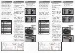
Plan Layout
1. There are 4 effective finger
lengths to choose from.
2. Select a finger length that best
suites the width of the crank shaft
pulley and belt.
3. Each finger (G or H) can be
mounted either in front of or
behind the Finger Mounting
Bracket (D).
4. Choose the appropriate finger
and mounting position according
to the pulley size and belt width.
5. Assemble the tool with your
chosen finger length and position
as shown in the kit list drawing
above.
6. Select the appropriate socket size
for the crank shaft pulley fixing
bolt (3/8˝D) and adjust the
Reaction Nut (C) so that the
operating face of the Finger
mounting bracket (D) is flat
against the face of the pulley and
the Metal Slotted Strap is parallel
to the face of the pulley (see
picture).
7. Feed the new belt around the
auxiliary drive pulleys leaving the
crank shaft pulley till last. Fit the
assembled and adjusted tool to
the crank shaft and fit the belt as
far round the crank pulley as is
possible by hand with the finger
of the tool under the belt as
shown below.
8. Using an appropriate wrench on
the hexagon end of the Square
Drive Shank (B) turn the
crankshaft of the engine in the
normal direction of rotation while
feeding the belt on to the pulley.
9. Important – once the belt is in
place, remove the tool and turn
the crank a further 2 turns and
check the belt is properly seated.
If required repeat the process to
lift the belt into correct alignment.
Method 1
Calibration
A. The tool can be assembled
without using the Slotted Strap
(A) and Square drive (B)
components to allow use where
access and clearance is
insufficient.
Method 2
Description
A
Metal Slotted Strap
B
Square Drive shank
C
Reaction Nut
D
Finger Mounting Bracket
E
Anchor Nut
F
Control Screw
G
Short Finger
H
Long Finger
I
Finger fixing screw
J
Hex Key
What is a stretchy / flexi belt?
Stretchy or Flexi Auxiliary Drive
Belts started to appear around
about 2004. They are made of a
material combination that gives
them some elastic like qualities.
These elastic qualities allow the
belts to be “stretched” into place for
fitting rather than having to back off
tensioners or pulleys.
These belt cannot however be
stretched into place by hand, they
require some form of tooling to
guide them on whilst the pulleys are
rotated.
The Stretchy Belt Installation tool
offers the user two methods of use
with four size options for the guide
fingers supplied in the kit.
Short finger position 1 & 2
Long finger position 1 & 2
c) Socket
b) Slotted Strap
a) Reaction Nut


