PLMNL0232 REV. H Effective Date: 01/14/19
62
FiberCUT
®
2D Operation Manual
14 Appendix G
– Servicing the Tip Assembly
14.1 Rebuilding the Tip Assembly
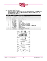
To disassemble the tip assembly:
1. Remove the tip assembly from the
head according to
2. Unthread the tip retainer nut assembly
and gas jet tip from the outer body.
3. Remove the (6) M3 SHCS
(PLSCR0109) securing the breakaway
insulator (PLISR0041) to the tip
assembly.
4. Remove the tip retainer nut and the
breakaway insulator with the o-rings
from the top plate.
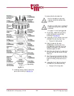
5. Inspect the large o-ring (PLMOR0029)
and the small o-ring (PLMOR0030) in
the breakaway insulator.
Replace any worn or damaged o-
rings.
6. Inspect the large o-ring (PLMOR0029)
and the small o-ring (PLMOR0030) in
the top plate.
Replace any worn or damaged o-
rings.
7. Remove the (3) M3 SHCS
(PLSCR0042) securing the top plate
to the outer body.
8. Remove the top plate and upper
insulator (PLISR0042).
The inner cone may come out with
the upper insulator.
9. Inspect the small o-ring (PLMOR0039)
near the bottom of the 2.5 mm
(smaller) gold post (PLSCR0112).
Replace the o-ring if it is worn or
damaged.
10. Inspect the o-ring (PLMOR0046)
around the upper insulator.
Replace the o-ring if it is worn or
damaged.
11. Inspect the small o-ring (PLMOR0030)
in the outer body.
Replace the o-ring if it is worn or
damaged.
12. Unthread the 5 mm (larger) gold post
(PLSCR0107) from the outer body.
13. Unthread the 2.5 mm (smaller) gold
post (PLSCR0112) from the inner
cone.
14. Remove the inner cone (PLTRE0350)
and lower tip insulator (PLISR0043)
from the outer body.
15. Inspect the large o-ring (PLMOR0029)
in the inner cone.
Replace the o-ring if it is worn or
damaged.


