PLMNL0199 REV. J Effective Date: 08/05/21
4
FiberCUT
®
ST Operation Manual
2.4 Fiber Input
The fiber input is where the fiber optic cable
plugs into the cutting head. See
There are several industrial standard styles
of fibers ends (QBH, QD/LLK-D, LCA,
Q5/LLK-B, HCL-8 & PIPA). See
for sample images of each. Each of
these fibers has a unique method of
securing it to the fiber input adapter. Refer
to the fiber
manufacturer’s information for
specific instructions.
2.5 Bundling
As in any robotic application, cables need
to be bundled in a manner allowing
complete tool movement without pinching
or pulling of the cables. The FiberCUT
®
head was designed so that all cables input
in the same location
– allowing a sleek,
easy-to-manage bundle.
Cabling should not be tethered to the fiber
input connector or the fiber optic cable.
The manner in which the cables are
bundled is one of the keys to having
a successful robotic cutting cell. The
end user is responsible for
documenting and training personnel
on the best bundling methods for
their application.
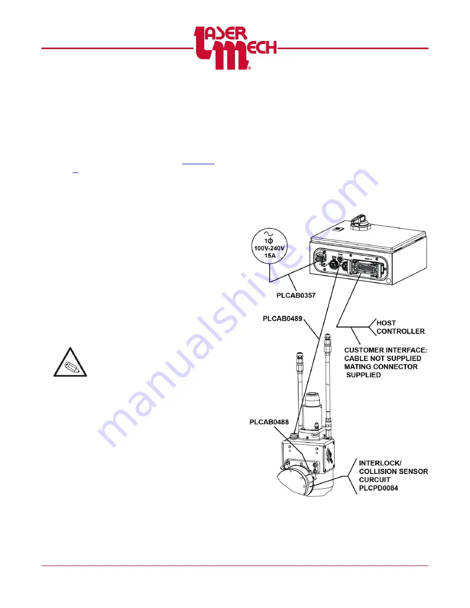
2.6 Electrical Wiring
There can be two electrical wires
connected to the cutting head. See
One is the communication cable
between the cutting head and the
control box (PLCAB0489).
The other is the optional collision
sensor cable that is plugged into the
robot system interlock (PLCAB0488).
Figure 7


