PLMNL0199 REV. J Effective Date: 08/05/21
7
FiberCUT
®
ST Operation Manual
3 Installation
– Electrical
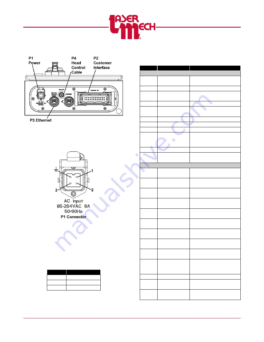
Figure 12
3.1 Power (P1)
Specifications: 85 to 264VAC, 50/60Hz,
6A
Figure 13
Power to the FiberCUT
®
controller is
connected using P1 (4-pin connector) on
the bottom left side of the control box. A
power cord is included with the system,
however alteration of this connection may
be preferred based on specific installation
requirements.
PIN
DESCRIPTION
1
Hot
2
Neutral
Ground
Ground
3.2 Customer Interface (P2)
PIN
NAME
DESCRIPTION
INPUTS
P2-1
Input-1 (HS1)
Height Select Bit 1
(LSB)
P2-2
Input-2 (HS2)
Height Select Bit 2
P2-3
Input-3 (HS3)
Height Select Bit 3
(MSB)
P2-4
Input-4 (COT)
Teach/Center of Travel
P2-5
Input-5
(HOLD)
Motion Inhibit/Hold
P2-6
Input-6 (TSB)
Tip Select Bit
P2-7
Input-7 (AIE)
Analog Input Enable
P2-8
Input-8 (RST)
Reset
P2-9
Input
Common
(IN-COM)
Input Common
P2-10
ANALOG-IN
Stand-off Height Select
P2-11
ANALOG-
GND
Analog Ground
OUTPUTS
P2-12
ANALOG-
OUT
Configurable Output
Voltage
P2-13
Output-1
(IN-POS)
In-Position
P2-14
Output-2
(RET-POS)
Retracted Position
P2-15
Output-3
(Tip Touch)
Tip Touch
P2-16
Output-4
(Crash)
Crash/Fault Active
P2-17
Output-5
(STAT1)
Status Code 1 (LSB)
P2-18
Output-6
(STAT2)
Status Code 2
P2-19
Output-7
(STAT3)
Status Code 3
P2-20
Output-8
(STAT4)
Status Code 4 (MSB)
P2-21
Output
Common
(OUT-COM)
+V-Sourcing,
0V-Sinking
P2-22
N/C
N/C
P2-23
INT1
Crash Interlock Relay
N/O, 60V, .5A Max
P2-24
INT2
Crash Interlock Relay
N/O, 60V, .5A Max


