PLMNL0199 REV. J Effective Date: 08/05/21
1
FiberCUT
®
ST Operation Manual
1 Introduction
The FiberCUT
®
robotic laser processing head
was developed to work in the most extreme
manufacturing environments. The straight input
of all connections, including the fiber, optimizes
the ability of the robot to utilize its complete
working envelope.
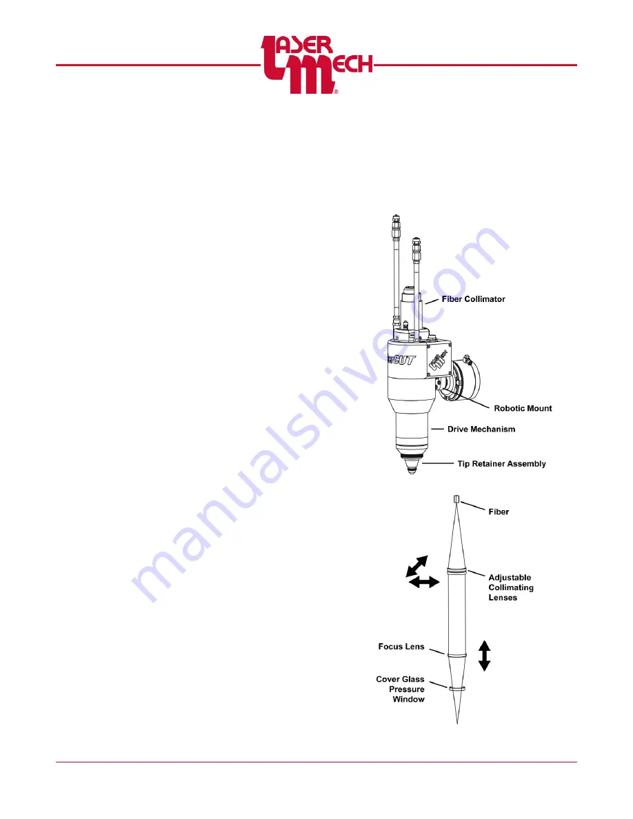
The FiberCUT
®
is made up of four main
subassemblies. See
The robotic mount
The fiber collimator assembly
The drive mechanism
The tip retainer assembly
for the path of the laser beam
through the FiberCUT
®
. The robotic mount
connects the cutting head to the robot, often
through an optional collision sensing device. The
fiber collimator unit uses a doublet collimating
lens to gather the laser light and collimate it after
it leaves the fiber optic cable.
A collimator focal length of 100mm is
standard (other focal lengths are available if
the application requires).
The laser beam then propagates through the
final focusing lens which focuses the laser
through the orifice of the gas jet tip. The drive
assembly provides the motion system that
allows the tip to track the surface of the part and
maintain laser focus.
The drive system has 25mm of travel and is
controlled by a patented drive system which
provides smooth, linear motion.
The tip retainer assembly contains the final
focusing lens and a cover glass that protects the
lens from dirt and debris. The lens housing is
threaded into the tip assembly.
The tip threads into the end of the tip
retainer and controls gas flow to the work
piece.
The tip retainer assembly also provides the
electrical feedback to maintain a constant
gap between the tip and part.
The tip retainer assembly comes in various
focal lengths and configurations, allowing
the end user to optimize the cutting head
configuration.
This manual explains the steps of installing,
setup, operation and service of a FiberCUT
®
robotic laser.
Figure 1
Figure 2


