ICS-6-DLSM Instruction Manual
01692-53-000
Page 10 of 20
Issue 3 30 January 2020
4.4 Override
Doors in the B area may be overridden by connecting external controls to the Switch Unit. The
override facility inside the B area ICS is not used at all.
The switching unit is equipped with an override buzzer and light to indicate when the B area is
overridden. The buzzer may be disabled by removing link LK1 ‘Buzzer Ctrl’ on the main PCB inside
the Switch Unit.
In general, doors in the A area are overridden by connecting the A area override device to the A ICS
in the usual way according to the ICS manual. More information is given below.
There are a number of ways of arranging for the B area interlocks to be overridden, as follows:
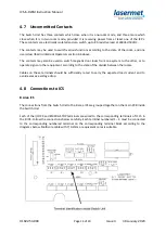
ICS-KP12 Keypad
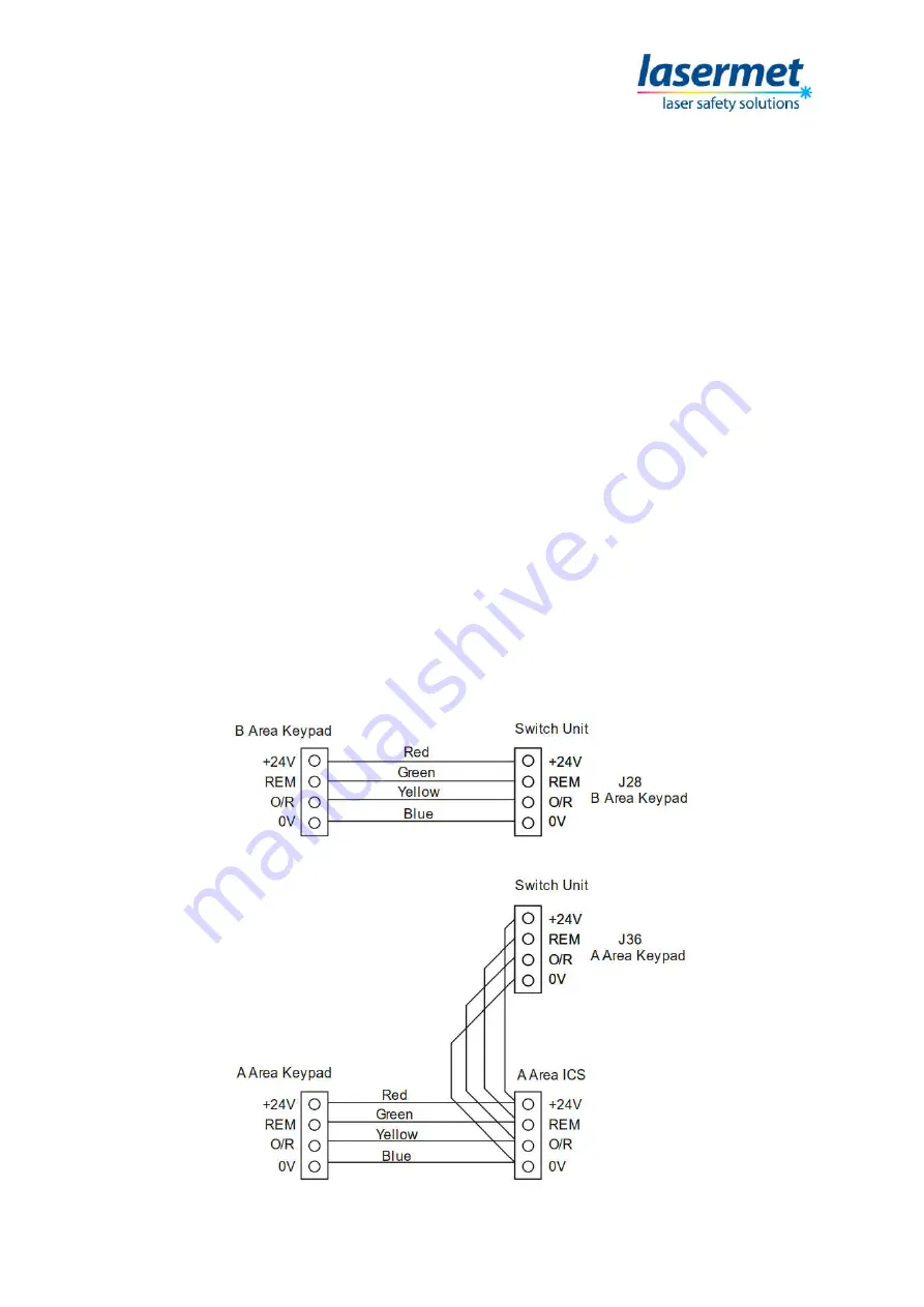
An ICS-KP12 keypad may be provided at one or more entry points into the B area. If this is done the
keypad should be wired to J28 B Area Keypad inside the Switch Unit. Each keypad terminal should be
wired to the terminal with the same name in the Switch Unit. Link LK2 must be fitted on the main
PCB inside the Switch Unit. If there is more than one keypad they should all be wired in parallel to
the same terminals. Keypads must not be wired to the ICS.
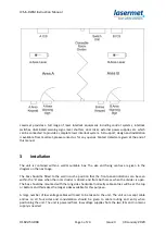
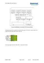
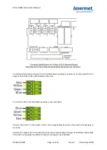
If there is a keypad in the A area it is connected as normal to the Keypad terminal block in the A area
ICS as shown in the ICS manual. If it is necessary for it to allow entry through doors in the B area in
one-room mode the four connections from the A area keypad should be taken to both the A ICS and
the A area keypad terminal block J36 in the Switch Unit, as shown on the next page.

