ICS-6-DLSM Instruction Manual
01692-53-000
Page 13 of 20
Issue 3 30 January 2020
If the signs in B area are powered from the 24V terminals of J7 ‘B ICS PWR OUT’ they will only
operate when the B ICS is switched on. If they are powered from J6 ‘+24V OUT’ they will operate
when either ICS is turned on, which means that they will operate in one-room mode even if the B ICS
is switched off. In either case J9 ‘0V’ should be used for the negative connection.
Refer to the ICS manual for examples of sign wiring, remembering to use the terminals in the Switch
Unit instead of those in the ICS’s. Note that signs larger than Lasermet’s miniature types will require
larger current-carrying cables.
4.6 Interlock Operators
Each ICS has interlock operator contacts which are used to control the laser. Depending on the
installation these contacts may operate laser interlocks or beam shutters. They may also be used to
control magnetic door locks or other equipment. These devices should be connected to the relevant
ICS following the instructions in the ICS manual such that each ICS can control the devices in its area.
If it is necessary for devices in B area to be operational when in one-room mode, the A ICS must have
sufficient interlock operator contacts to control all the devices in both areas. This will often mean
that it should be equipped with a 9-way interlock board which gives nine interlock operator contacts
instead of the usual three.
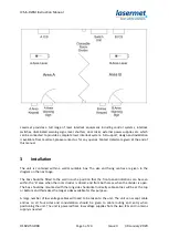
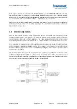
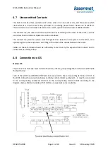
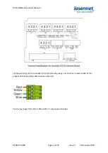
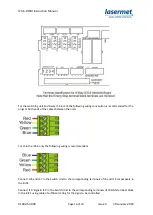
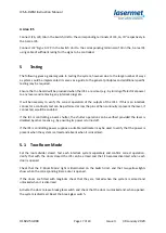
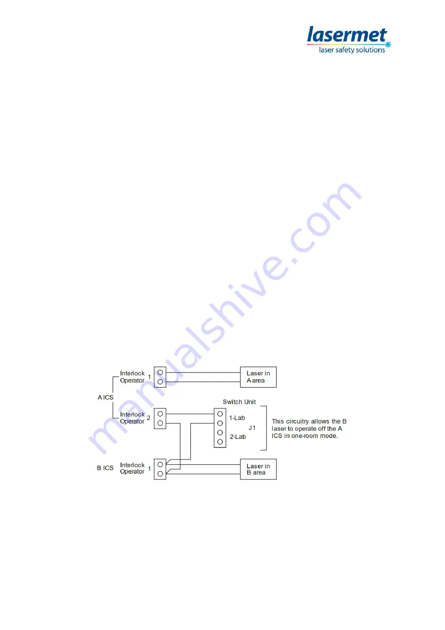
The Switch Unit has three pairs of uncommitted relay contacts as described in section 4.7 which
switch according to the state of the unit. These contacts are rated at 8A and may be used to connect
unused A ICS interlock operators in parallel with B interlock operators so that devices connected to
the B ICS may also be operated in one-room mode, as shown below.

