ICS-6-DLSM Instruction Manual
01692-53-000
Page 14 of 20
Issue 3 30 January 2020
4.7 Uncommitted Contacts
The Switch Unit has three contacts which close when it is one-room mode, and three more which
close when it is in two-room mode, provided it is receiving power from at least one of the ICS’s.
These contacts are electrically isolated and can switch up to 8A resistive load at 240Vac/50VDC.
The contacts may be used to switch various functions according to the state of the room, and one
use is described in Interlock Operators section 4.6 above.
The contacts may also be used to switch magnetic door locks from one system to the other, or to
operate signs or other equipment according to the state of the divider between the rooms.
Cables on these terminals should be sufficiently rated to carry the expected load current and to
avoid excessive voltage drop.
4.8 Connections to ICS
B Area ICS
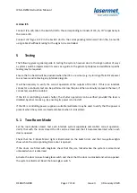
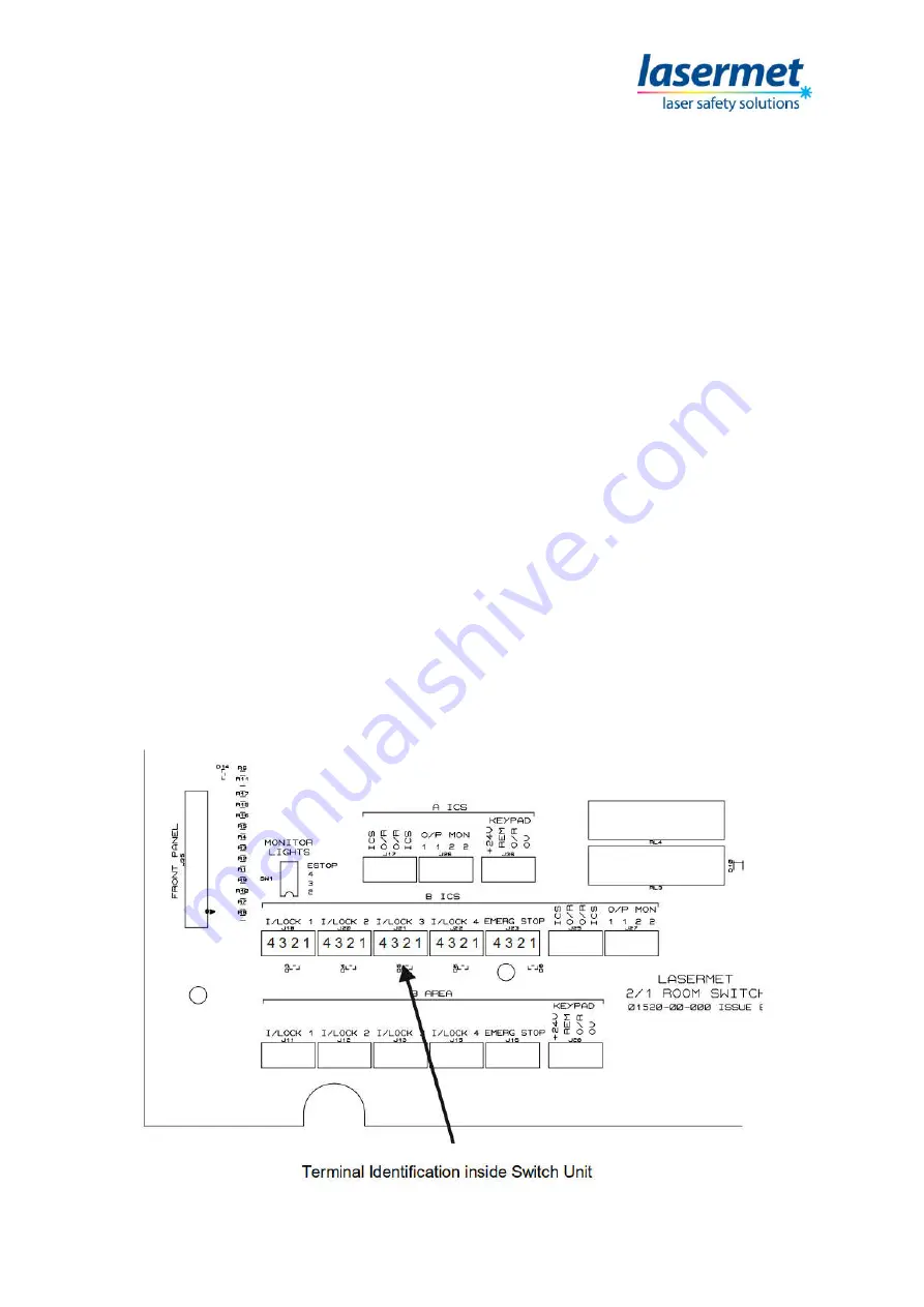
The connections from the Switch Unit to the B area ICS are grouped together on the main PCB inside
the Switch Unit.
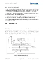
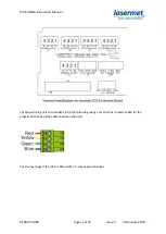
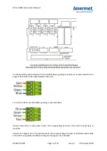
Each of the I/LOCK and EMERG STOP terminals are wired to the corresponding terminals of J1-J5 in
the B ICS. Follow the connections below carefully. Each terminal numbered 1 – 4 must be connected
to the corresponding numbered terminal on the corresponding terminal block according to the
diagrams below. Multicore cable with 7/0.2mm or equivalent cores is suitable.

