ICS-6-DLSM Instruction Manual
01692-53-000
Page 17 of 20
Issue 3 30 January 2020
A Area ICS
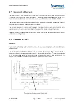
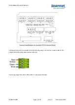
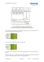
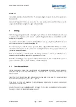
Connect J26, J29, J36 in the Switch Unit to the corresponding terminals of J14, J6, J17 respectively in
the A area ICS.
Connect J32 ‘Signs A ICS’ in the Switch Unit to the corresponding terminals of J8 in the A area ICS
using cable of sufficient rating for the signs to be controlled.
5
Testing
The following gives a general guide to testing the system, however due to the large number of ways
a system could be implemented it serves as a guide to the general principles and additional specific
testing may be required.
Ensure that no hazard will be produced when the ICS’s are armed, e.g. by turning off electrical power
to any lasers and removing any interlock plugs etc.
It will be necessary to verify the correct operation of the outputs of the ICS’s. If this is an interlock
connector a continuity test can be performed across the pins. When continuity is present the laser, if
connected, would be enabled.
If the ICS is controlling a beam shutter, the shutter operation can be verified provided the laser is
disabled by other means e.g. by ensuring its power is turned off.
If the ICS is controlling power supplies a suitable multimeter may be used to verify that the power is
present when the system is armed and absent when it is disarmed.
5.1 Two-Room Mode
Set the room divider closed. Test each interlock system separately and confirm correct operation.
Verify that with the doors closed the ICS can be armed and that it becomes disarmed when each
door is opened.
Check that the ‘2-Room Mode’ light is illuminated on the Switch Unit, and that two yellow lights
show when the corresponding B area door is opened.
If the doors are fitted with maglocks check that they are locked when the system is armed and
unlocked when it is disarmed.
Activate the door release break glass switch and check that the door is unlocked and, when opened,
the system is disarmed. Reset the break glass switch.

