ICS-6-DLSM Instruction Manual
01692-53-000
Page 4 of 20
Issue 3 30 January 2020
2
Concept
This unit is intended to simplify the implementation and operation of interlock systems where the
room comprises a divider such that it may be split into two sub-rooms each with its own ICS, or
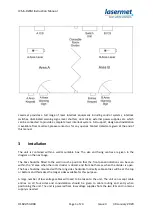
becomes one larger room when the divider is open, controlled by one of the ICS’s. A typical layout is
shown on the next page.
This version of the unit is compatible with Lasermet’s ICS-6 Interlock Controllers and cannot be used
with ICS-5.
In this manual it is assumed that when the divider is closed the room is divided into two areas
labelled herein as ‘A’ and ‘B’, each of which has its own interlock system which operates
independently of the other. In this manual the system is said to be in ‘two-room mode’ when the
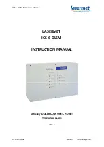
divider is closed. On the front panel of the switch unit, area A is referred to as ‘Area 1’, and area B as
‘Area 2’, to avoid confusion with the two safety input channels which are also labelled ‘A’ and ‘B’.
When the divider is open the ‘A’ area ICS takes control of the whole room and the ‘B’ area ICS is
disabled. This is said to be ‘one-room mode’.
The switching unit is versatile and can be wired such that the signs, overrides and controlled devices
such as lasers and shutters in the B area become controlled by the A ICS when in one-room mode. It
also allows the A area override device to override the B area interlocks and the B area override
device to override the A area interlocks in one-room mode.
The unit provides a duplicate of the B area interlock indications so the status of the B area doors can
be seen on the switching unit even if the B ICS is turned off.
The switching unit is normally set up to operate automatically according to the state of the room
divider, but it can be operated by switches or other means.

