ICS-TOUCH Instruction Manual
CEB00XXX-53-000
Page 10 of 43
Issue 4 19 January 2021
6
Wiring
ICS-6-SP Fail-safe Laser Interlock Controller
The ICS-6-SP Control Unit is a versatile interlock system and there are a variety of ways in which it
can be used. Be sure you know which configuration you require before you attempt to wire the unit.
If you require further assistance, please call Lasermet technical help. Contact details are at the end
of this manual.
A 2.5mm slotted screwdriver will be needed to access the screw terminals.
6.1 Power In
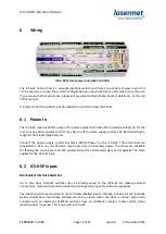
The ICS-6-SP requires 24VDC power. The power supply should be able to provide at least 1A for the
unit, plus any other equipment that may be run off the same supply such as 24V illuminated signs,
magnetic door locks (maglocks) etc.
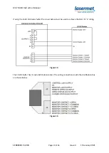
Connect the power supply to terminal block ‘24VDC Power’ on the ICS-6-SP. Three terminals are
provided for +24V, any one of which may be used for the incoming power. The others are available
for feeding the touch panel and 24V equipment such as illuminated signs and maglocks. The same
applies for the 0V terminals.
6.2 ICS-6-SP Inputs
Mechanical Interlock Switches
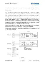
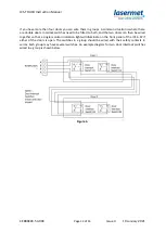
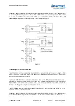
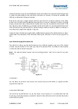
Up to four door interlock switches may be directly wired to the ICS-6-SP. By making external
connections, more switches can be added and arranged in groups for indication purposes.
The interlock switches are wired to the terminals labelled Input 1 through to Input 4. Each interlock
switch should have two safety contacts which are closed when the door is closed. Some door
contacts such as Lasermet’s IS-MECH switches have an additional monitor contact which closes
when the door is opened. This is not used in ICS-6-SP.

