background image

ICS-TOUCH Instruction Manual 


CEB00XXX-53-000 

Page 24 of 43


Issue 4          19 January 2021 


Override Switch without Timer 

 
It  is  possible  to  configure  the  ICS-6-SP  to  give  an  unlimited  override.  This  may  be  useful  for 
maintenance  purposes  or  when  the  access  door  may  be  open  for  some  time.  In  general,  such  an 
arrangement  may  require  additional  site  procedures  to  ensure  safety  while  the  interlock  is 
overridden. 
 
The override device may be a switch or other contact which remains closed for the duration of the 
override. A key-operated switch may be preferable to prevent unauthorised use. 
 
If a maglock is fitted to the door the override switch needs an additional contact which opens when 
activated, so that the lock is disabled allowing the door to be opened. 
 
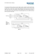
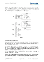
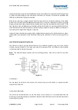
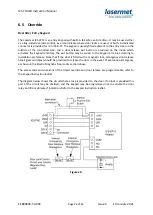
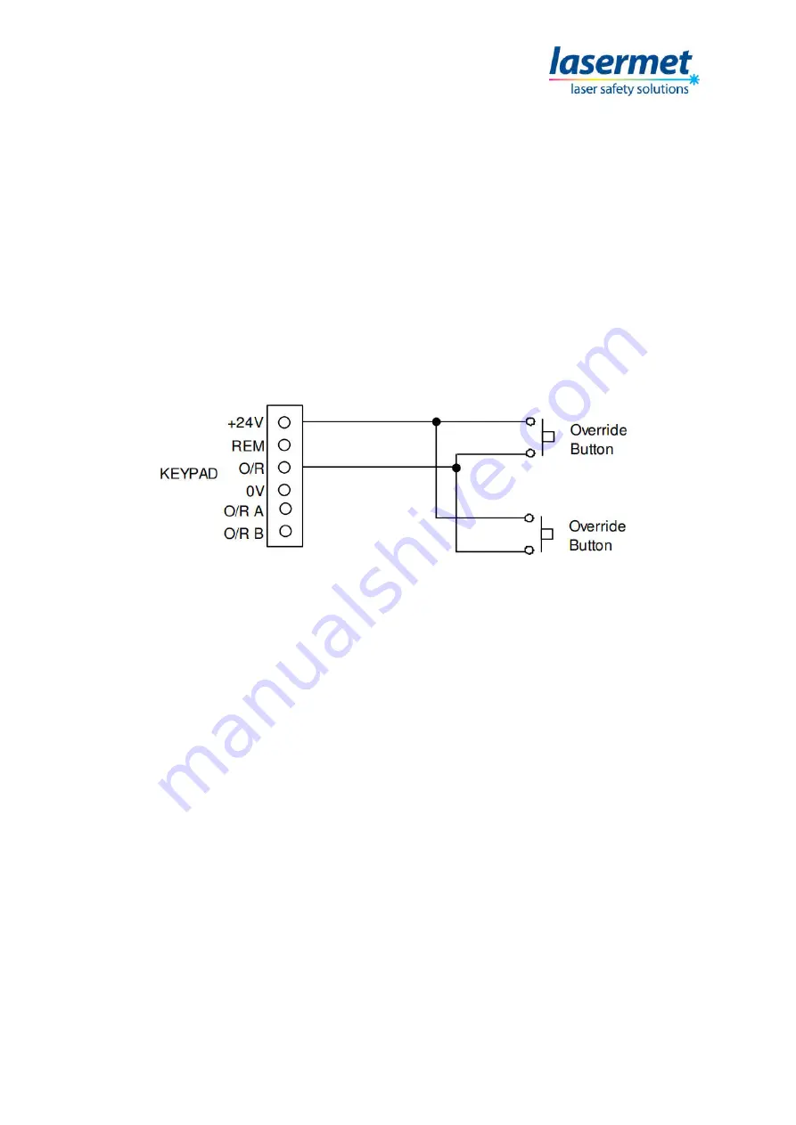
The override control contact is wired as shown below. 


Figure 21. 

 
The buzzer may be unnecessarily annoying in this mode of operation so it may be disabled.  


Local Override 

 
Where there are several entrances to the laser enclosure it may be desirable for the override to be 
only  applied  to  a  particular  entrance,  such  that  the  laser  will  be  disarmed  if  another  entrance  is 
opened while the override is active.  
 
To achieve this, the overriding device needs to have two isolated contacts which close to bypass the 
safety contacts of the relevant door switch, and a third contact to activate the override indications 
on the ICS-6-SP. If a maglock is fitted to the door the overriding device needs a fourth contact which 
opens when activated, so that the lock is disabled allowing the overridden door to be opened. 
 
Lasermet  offer  the  ICS-KP14  which  provides  this  functionality.  Refer  to  the  ICSKP14  manual  for 
specific details. 
 
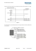
When  this  mode  of  operation  is  used  it  is  essential  that  the  override  function  on  the  ICS-6-SP  is 
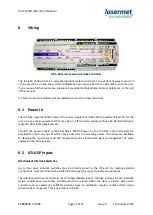
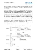
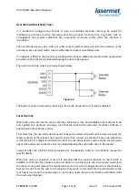
disabled so that the other inputs are not overridden. To do this locate the ‘Annun only’ marking on 
the ICS and unclip and remove the associated cover to access the configuration link as shown below. 
Remove the link to set the unit to Annunciation Only mode. In this mode the ICS will indicate on the 
touch panel and sound its buzzer when an override is active but will not itself be overridden. Refit 
the cover when finished. 

Summary of Contents for ICS-6-SP

Page 1: ...ICS TOUCH Instruction Manual CEB00XXX 53 000 Issue 4 19 January 2021 LASERMET ICS TOUCH and ICS 6 SP Control Unit INSTRUCTION MANUAL INTERLOCK CONTROL SYSTEM WITH SURGEON S PANEL ...

Page 2: ...13849 1 2015 7 5 Installation 8 5 1 Positioning 8 6 Wiring 10 6 1 Power In 10 6 2 ICS 6 SP Inputs 10 6 3 ICS 6 SP Illuminated Sign Control Output 15 6 4 Output Contacts 17 6 5 Override 23 7 Expansion Boards 26 7 1 Installing Expansion Boards 26 8 Mismatch Detector 27 8 1 Configurable Options for Safety Circuit Mismatch Events 27 8 2 Clearing a Mismatch Fault Indication 28 8 3 Mismatch Detector Rem...

Page 3: ... Interlock Inputs 31 11 2 Emergency Stop Input 32 11 3 Pre arm and Expansion Status 33 11 4 Mismatch Indication and Reset 34 11 5 Safety Circuits OK Indication 35 11 6 Arming the Interlock Controller 35 11 7 Arming Indication 36 11 8 Override Indication 36 11 9 Language Options 37 12 ICS TOUCH Access Control using PIN 38 12 1 Lock Status Display 38 12 2 PIN Entry 39 13 Fuses 41 14 Specifications 4...

Page 4: ...s that this product complies with the basic requirements for health and safety as provided by the following directives and standards Directives Machinery Directive 2006 42 EC June 2010 Low Voltage Directive 2014 35 EU EMC Directive 2014 30 EU Standards EN ISO 13849 1 2015 Safety of Machinery Safety related parts of Control Systems EN 60947 1 2007 A1 2011 A2 2014 Low Voltage Switchgear and Controlg...

Page 5: ...meters contained herein The units are only designed to be fixed to surfaces using their inbuilt fixing holes They must not come into contact with each other or any other moving part when in use The parts should never be subject to impact or mechanical strain Safety switches should never be defeated or bypassed It is imperative that all steps are taken to ensure that any spare actuators are made un...

Page 6: ... the system The ICS 6 SP has a fully dual channel cross checked architecture and when correctly wired can realise a system compliant with EN ISO 13849 1 up to performance level e Three safety interlock outputs each rated at 6A resistive 250Vac are provided to enable the laser operate door locks etc The interlock outputs are volt free contacts which close when the system is armed Each contact actua...

Page 7: ...ovide a complete laser interlock system Full support design and installation is available from Lasermet please contact us for any queries Contact details are given at the end of this manual 4 Summary of Evaluation of Compliance to EN ISO 13849 1 2015 To achieve a complete system performance level e the system must be wired as described in this manual using suitably rated door sensors and measures ...

Page 8: ...nnected to the ICS 6 SP Control Unit via a supplied RS 232 lead 5 1 Positioning The ICS 6 SP Control Unit should be mounted in a convenient position for wiring It should be inaccessible by operators It has indicator lights on its top surface which would normally only need to be observed by installation and maintenance personnel Provision should be made to prevent the unit from sliding along the DI...

Page 9: ...arest the edge of the label on a pink background are the identifications of the bottom row terminals Next to these on a green background are the identifications for the top rows of terminals In the yellow box there are indication lights which light up when the unit incoming power is on expansion socket power is on and when the two output channels are armed ...

Page 10: ...minated signs magnetic door locks maglocks etc Connect the power supply to terminal block 24VDC Power on the ICS 6 SP Three terminals are provided for 24V any one of which may be used for the incoming power The others are available for feeding the touch panel and 24V equipment such as illuminated signs and maglocks The same applies for the 0V terminals 6 2 ICS 6 SP Inputs Mechanical Interlock Swit...

Page 11: ...eason simultaneously it may also be necessary to route the cables in different paths If the laser hazard is considered low it is possible to use switches with only one safety contact In this case connect the switch across the A terminals Fit a wire link across the B terminals The Mismatch Detector cannot be used and must be disabled see the Mismatch Detector section below It is usual to use low vo...

Page 12: ...witches need to be fitted to both and the two doors can then be wired together so that a single monitor indication light will illuminate on the front panel of the ICS 6 SP if either of the doors is open The switches in a group should be wired with their safety contacts in series Each group may have several switches An example diagram for two door interlock switches wired in a group is shown below ...

Page 13: ...cuits in the same way as described in the Mechanical Interlock Switches section The monitor contacts should not be used The Lasermet IS MDC 12 is a dual channel magnetic door switch If the mismatch detector is used in the ICS 6 SP any single contact failure in the door switch will be detected and the laser inhibited In this switch the red and blue wires are taken to the A terminals and the black a...

Page 14: ...If there are two or more switches connect the contacts in series as shown below Figure 6 As mentioned in the interlock switches section above if the laser hazard is low and the emergency stop switch has sufficient safety integrity it may be acceptable to use a switch with just one contact The switch should be wired across the A terminals and a wire link fitted across the B terminals The ICS 6 SP m...

Page 15: ...s armed Figure 7 Option 2 Two way Illuminated Warning Sign The first warning sign will come on when the ICS 6 SP is powered The first warning sign will go off and the second warning sign will come on when the Arm Laser button is pressed Figure 8 Low Voltage DC Warning Signs The following options are for 24VDC warning signs such as Lasermet s Miniature and Ultra Warning Signs These signs must not b...

Page 16: ...The first warning sign will go off and the second warning sign will come on when the unit is armed Note that in the case of the Lasermet Miniature and Ultra 2 way warning signs both indications are displayed in the same unit Figure 10 Note regarding Sign Operation If output devices such as LS 20 shutters or contactors are fitted or if the laser has feedback contacts which close to prove that it is...

Page 17: ...e or circuit breaker not exceeding 5A rating To avoid risk of shock always ensure the mains supply is isolated before making these connections Be sure to use suitable mains rated wiring and ensure compliance with local electrical wiring regulations Figure 11 The contact is rated at 4A resistive load maximum If the laser mains supply requirement exceeds the capability of the ICS 6 SP please contact...

Page 18: ... laser s own interlock if a high safety integrity is required Lasermet s beam shutters are supplied with suitable leads to plug into the distribution boxes Open ended leads are provided for laser interlocks allowing the customer to fit the correct plug for his laser Laser Shutter Supply 4A maximum The ICS 6 SP is able to provide both continuous and switched supplies using one of the Output contact...

Page 19: ...Issue 4 19 January 2021 If using the LS 20 SIL3 twin shutter the circuit below must be used to achieve the SIL3 PL e rating Figure 13 The LS 20 Shutter has its own distribution socket The wiring connections inside the distribution box are shown below Figure 14 ...

Page 20: ... operate a laser s interlock control provided they haven t been used for any other purpose The contacts are closed when the ICS 6 SP Control Unit is armed If there is more than one laser each must use its own output connector on the ICS 6 SP Control Unit Interlock sockets of several lasers must not be connected together Where the controller is part of a fixed laser system it is usual to directly c...

Page 21: ...ign and arming will be inhibited Depending on the safety performance of the laser itself such a system could meet EN 13849 1 performance level e The wiring of such a laser is shown below Please contact Lasermet for assistance with distribution boxes connectors and leads if required If other devices are using the Output Monitor terminals for example an LS 20 shutter all the safe proving contacts fo...

Page 22: ...s switch Figure 19 Note that several maglocks can be wired in parallel from the same ICS 6 SP Control Unit output provided the 4A maximum rating of the contact is not exceeded Some locks can be configured for 12V or 24V supply They should be set for 24V operation and run off the 24V supply to reduce the current consumption to 0 25A per lock To set Lasermet Maglocks for 24V operation open the termi...

Page 23: ... remotely The exit button may be wired to the keypad or ICS 6 according to installation preference Note that if the door is fitted with a magnetic lock emergency door release break glass switch es should be provided to release the door in the event of evacuation emergency as shown in the Electro Magnetic Door Locks section above The access code and durations of the timed override and door release ...

Page 24: ...able for the override to be only applied to a particular entrance such that the laser will be disarmed if another entrance is opened while the override is active To achieve this the overriding device needs to have two isolated contacts which close to bypass the safety contacts of the relevant door switch and a third contact to activate the override indications on the ICS 6 SP If a maglock is fitte...

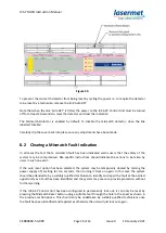
Page 25: ...udible Override alarm inside the ICS 6 SP which is enabled when the O R Buzzer jumper is fitted on the unit To access the configuration link locate it using the label on the unit and unclip and remove the cover see the diagram above Refit the cover when finished The touch panel indicates when the override is in operation ...

Page 26: ...l crosschecked and does not use processors or software Programming is achieved through hardwiring This means obsolescence is minimised and the system is maintainable for a long service life The Interface Board allows ICS 6 SP Control Unit to read the output of a Safety Logic Plus system whilst automatically testing it and providing fault protection Relay Expansion Card This module contains a numbe...

Page 27: ...atch Event Behaviour In the event of a mismatch being detected either of the following two actions are available depending on the option switch settings a Lock out preventing further use unless the system is reset by switching it off and on again b Lock out preventing further use unless the system is attended to by a qualified technician Option a is suitable for mission critical applications where...

Page 28: ...e safety of the system may be compromised Site specific instructions should indicate the actions to be taken by users in such an event If the auto reset option has been selected the system may be temporarily cleared by turning the power supply off waiting for ten seconds then turning it back on again In this case the system should be attended to by a suitably qualified technician to identify and r...

Page 29: ...which closes momentarily to reset the detector If the test function is not used a wire link must be fitted across the Test terminals Contact Lasermet or your local distributor for assistance if you wish to use these features 9 LED Indicators The ICS 6 SP relies on its associated touch panel to provide an operator interface and the LED s on the unit provide very basic information to service personn...

Page 30: ...bol and indicate that the laser is enabled On the Controller unit the amber Armed A and B lights will be illuminated Note Be aware that this action restores power to the shutters or the laser and may result in accessible laser beams depending on your system set up The system should only be armed when everyone is ready and the necessary safety precautions have been taken e g protective eyewear etc ...

Page 31: ...ue 4 19 January 2021 11 ICS TOUCH User Interface Status Display 11 1 Interlock Inputs The state of up to four separate interlock inputs is shown by door icons which change colour according to the state The interlocks have two redundant channels to maximise safety ...

Page 32: ...ICS TOUCH Instruction Manual CEB00XXX 53 000 Page 32 of 43 Issue 4 19 January 2021 11 2 Emergency Stop Input The state of the emergency stop input is shown in the same way using a mushroom button icon ...

Page 33: ...e laser will not immediately radiate when the interlock controller is armed The pre arm loop is normally closed before arming and is opened by the interlock controller when the system is armed so at this point the state should change from green closed to red open It is possible to extend the interlock controller with add ons connected via the expansion socket The safety loop status of expansion un...

Page 34: ...sing If this occurs a fault condition will be indicated and the fault condition will be latched until reset Note that a short period of mismatch is allowed by the interlock controller because two switches will never close at exactly the same time The mismatch is indicated by an icon on the display and a touch button is provided to reset the fault condition after the fault has been rectified Touchi...

Page 35: ... the Interlock Controller The ICS 6 SP offers two options for arming either a physical push button connected directly to the interlock controller or a touch button on the ICS TOUCH display If the display touchscreen is to be used a button will be displayed in one of three different states depending on the arm status When the touch button is pressed the panel sends a message to the ICS 6 SP The int...

Page 36: ...rm button indicates the arming status 11 8 Override Indication The ICS TOUCH has an override input which allows the safety interlocks but not the emergency stop to be temporarily overridden This is normally used with a Lasermet keypad to provide a coded door override Use of the override is indicated by a flashing keypad icon on the display ...

Page 37: ...ault language However it can be configured for French German or Turkish To switch to another language navigate to the Admin Page by pressing the lock icon This will prompt for the admin password The default admin password is 1234 On the Admin Page press on the dropdown textbox and select a language Use the up and down arrow keys to navigate ...

Page 38: ...two possible methods of access control either a physical keyswitch wired directly to the interlock controller or a PIN entered via a keypad on the ICS TOUCH 12 1 Lock Status Display Using either method of access the ICS 6 SP may be locked or unlocked This is indicated by an icon to the left of the status display which also acts as a touch button ...

Page 39: ... opened The user then enters a 4 digit PIN using the numeric touch keys and the backspace key if necessary to correct errors Four dots are displayed above the keypad and the unit bleeps for each key press The default PIN is 3333 When all four digits have been entered the user presses the enter key For a successful entry the following screen is displayed ...

Page 40: ... then sends a return message to display the unlocked status There may be a brief delay while this happens If the PIN fails the following display is seen and the status screen is shown after a short delay If the user has entered the correct PIN and elects to change the PIN the PIN entry screen will remain the four dots will be cleared and the user can enter the new PIN Since this is automatically v...

Page 41: ... 20 X 5mm F2 B Safety Loop 315mA 20 X 5mm F3 Expansion Module 24V Power 3 15AT 20 X 5mm 14 Specifications Safety Performance Up to PL e to EN ISO 13849 1 2015 see section 4 Shutdown Time 6ms typical Measured from opening of safety circuits to opening of interlock operator contacts Maximum Safety 220Ω at 24V supply voltage Loop Resistance 140Ω at 21 5V supply voltage Supply Voltage 24V DC 21 5 26 5...

Page 42: ...fects in workmanship for 12 months Damage or defects caused by other factors are not covered For example industrial contamination incorrect cleaning storm damage Consequential loss is not covered under warranty Compensation for indirect or direct loss or damage is expressly excluded Rectification of the defects or a replacement does not initiate a new warranty period For all deliveries payments an...

Page 43: ...provide a complete system We also supply equipment and consultancy covering all aspects of laser safety Full support design and installation is available from Lasermet please contact us for any queries For sales and technical support Lasermet Ltd Lasermet House 137 Hankinson Road Bournemouth BH9 1HR United Kingdom Tel 44 0 1202 770740 Fax 44 0 1202 770730 Email sales lasermet com Website www laser...

Reviews: