ICS-6 Instruction Manual
01000-53-000
Page 11 of 42
Issue 11 19 January 2021
5.1.2
ICS-6-24
(24VDC)
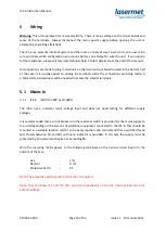
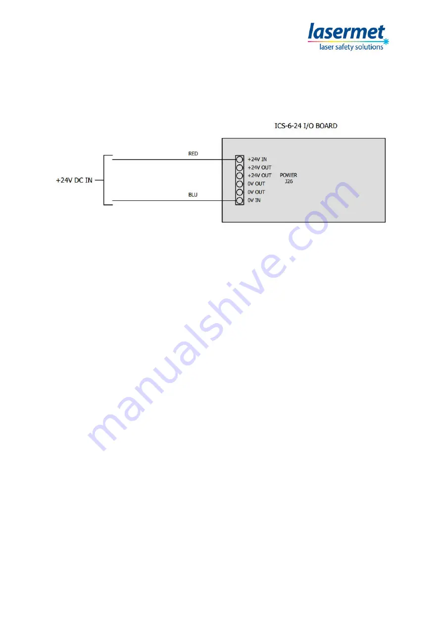
Using the ICS-6-24 I/O board, the ICS-6 can be configured to operate at 24VDC.
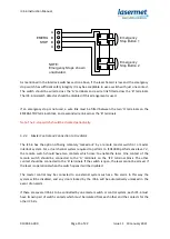
Wire the 24V power supply to the following terminals on the ICS-6-24 I/O board.
Power supply must be at least 100W. Lasermet provides an appropriate 24V power supply. Contact
details given at the end of this manual.
5.2 ICS-6 Inputs
5.2.1
Mechanical Interlock Switches
Up to four door interlock switches may be directly wired to the ICS-6. By making external
connections, more switches can be added and arranged in groups for indication purposes.
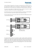
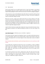
The interlock switches are wired to the terminals labelled INTERLOCK 1 through to INTERLOCK 4.
Each interlock switch should have two safety contacts which are closed when the door is closed.
Some door contacts such as Lasermet’s IS-MECH switches have an additional monitor contact which
closes when the door is opened. This is not used in ICS-6.
A 4-way terminal block is provided for each door interlock switch. One of the safety contacts which
are closed when the door is closed is wired to the ‘A’ terminals. The other safety contact is wired to
the ‘B’ terminals.
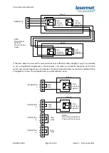
If the system is required to perform to ISO 13849 performance level ‘e’, two switches are usually
required to be fitted to each door, with the safety contact of one switch wired to the ‘A’ terminals
and the safety contact from the second switch wired in a separate cable to the ‘B’ terminals. If there
is any possibility of both cables being damaged for the same reason simultaneously it may also be
necessary to route the cables in different paths.

