ICS-6 Instruction Manual
01000-53-000
Page 15 of 42
Issue 11 19 January 2021
A
B
B
A
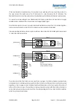
EMERG
STOP
Emergency
Stop Button 1
NOTE:
Em ergency Stops shown
unactivated.
Emergency
Stop Button 2
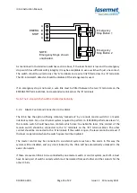
As mentioned in the interlock switches section above, if the laser hazard is low and the emergency
stop switch has sufficient safety integrity it may be acceptable to use a switch with just one contact.
The switch should be wired across the ‘A’ terminals and a wire link fitted across the ‘B’ terminals.
The ICS-6 mismatch detector should be disabled if this arrangement is used.
If an emergency stop is not used, a wire link must be fitted between the two ‘A’ terminals on the
EMERG STOP terminal block, and a second wire link across the ‘B’ terminals.
Note. The E-stop switch should be checked periodically.
5.2.4
Master Control and Connection to Fire Alarm
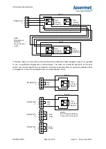
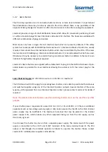
The ICS-6 has the option of being remotely ‘locked out’ by a remote master switch or a master
interlock system. For a dual channel system required to perform to ISO13849 performance level ‘e’,
the remote switch should have two contacts which close to enable the laser. One contact of the
remote switch should be connected to the ‘A’ terminals on the ‘ICS’ terminal block. The other
contact should be connected to the ‘B’ terminals. If the switch is open, the laser cannot be armed. If
the laser is operational when the switch opens it will be disabled.
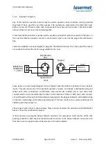
The master control may be connected to an external system such as a fire alarm. In this way the
system will be disabled, and any doors locked by the ICS-6 will be automatically unlocked in the
event of an alarm.
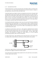
If there are several ICS-6’s to be controlled by one master switch or control system, each ICS-6 must
have its own pair of switch contacts which must be isolated from each other and the contacts for the
other ICS-6’s.

