background image

 
ICS-6 Instruction Manual 


01000-53-000 

Page 31 of 42 

Issue 11    19 January 2021 


6.2  Installing Expansion Boards 

 
It  is possible to install  one  expansion board  into  a standard ICS-6,  however  the  space  for  wiring  is 
fairly  restricted  so  a  deep  case  option  is  available  for  ICS-6  which  increases  the  depth  of  the  unit 
from 89mm to 145mm, which gives ample space for three or four expansion boards. 
 
Note that the O-PCB override timer cannot be fitted at the same time as an expansion board. 
 
To fit an expansion board, turn off and isolate the mains supply and open the ICS-6. 
 
On the large circuit board on the inside of the ICS-6 cover, remove the ICS Expansion Control Socket 
Terminator near the top right corner. Do not discard it as it will be needed shortly. 
 
Locate the Expansion board onto the sockets on the large circuit board on the back of the door, such 
that  the  holes  in the  expansion  board align with the  screw  pillars  in the  circuit  board behind.  It  is 
most important that the holes are aligned with the pillars behind. Insert two M3 screws with shake 
proof washers through the holes in the expansion board to secure it to the pillars. It is essential that 
the expansion board is fitted the right way round and secured with the screws as it may otherwise 
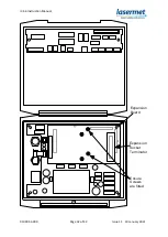
fall off, disabling the system. Refer to the diagram on the next page. 
 
Make  the  necessary  electrical  connections  to  the  expansion  board  according  to  its  specific 
instructions. 
 
If  further  expansion  boards  are  required,  fit  each  one  on  top  of  the  previous  one  using  the  same 
method and ensuring that each is secured to the one below using the screws. It is usually easiest to 
wire each one before fitting the next one on top. 
 
Refit  the  ICS  Expansion  Control  Socket  Terminator  to  the  socket  in  the  top  right  corner  on  the 
topmost expansion board as shown on the next page. 

Summary of Contents for ICS-6

Page 1: ...ICS 6 Instruction Manual 01000 53 000 Issue 11 19 January 2021 LASERMET ICS 6 INSTRUCTION MANUAL FAIL SAFE LASER INTERLOCK CONTROL SYSTEM ...

Page 2: ... 2 ICS 6 24 24VDC 11 5 2 ICS 6 Inputs 11 5 2 1 Mechanical Interlock Switches 11 5 2 2 Coded Magnetic Interlock Switches 14 5 2 3 Emergency Stop and Break Glass Switches 14 5 2 4 Master Control and Connection to Fire Alarm 15 5 3 ICS 6 Illuminated Sign Control Output 16 5 3 1 Low Voltage DC Warning Signs 16 5 4 Interlock Operator Output Contacts 18 5 4 1 Laser Power Supply 18 5 4 2 Beam Shutters 19...

Page 3: ...tion 30 6 2 Installing Expansion Boards 31 7 Mismatch Detector 33 7 1 Description 33 7 2 Configurable Options for Safety Circuit Mismatch Events 33 7 3 Clearing a Mismatch Fault Indication 34 7 4 Remote Test and Reset 35 8 LED Indicators 36 9 Operation 38 9 1 Starting Up 38 9 2 Resuming Operation after an Interlock Switch has been opened 38 9 3 Using the Override 39 10 Specifications 40 11 Warrant...

Page 4: ...es that this product complies with the basic requirements for health and safety as provided by the following directives and standards Directives Machinery Directive 2006 42 EC June 2010 Low Voltage Directive 2014 35 EU EMC Directive 2014 30 EU Standards EN ISO 13849 1 2015 Safety of Machinery Safety related parts of Control Systems EN 60947 1 2007 A1 2010 A2 2014 Low Voltage Switchgear and Control...

Page 5: ...ling to open the other contact will open and the system is then disabled preventing further use and maintaining safety The contacts can be configured for a variety of options The ICS 6 is available in enhanced versions which offer the following options Nine Interlock Output contacts seven rated at 8A 50VDC maximum and two rated at 8A 250Vac Three pole safety power contactors which may be used to s...

Page 6: ...rmet have a range of modules either available or in development including Uncommitted Relays Active Beamguard Safety Logic Plus Network Interface Lasermet provides a full range of equipment including interlock switches illuminated warning signs laser shutters entry keypads with built in fail safe override timer door locks external power supplies etc which can be connected to the ICS 6 to provide a...

Page 7: ...eir inbuilt fixing holes They must not come into contact with each other or any other moving part when in use The parts should never be subject to impact or mechanical strain Safety switches should never be defeated or bypassed It is imperative that all steps are taken to ensure that any spare actuators are made unavailable such that they cannot be used to defeat the switch or reduce the protectio...

Page 8: ...anual using suitably rated door sensors and measures taken to minimise the effects of common cause failures in the sensors and wiring which may be connected to the unit Required Characteristics Architecture Category 3 4 Performance Level Required PLr PLr e Application Demand Base In service operation 365 days year Functional demand on the controller once per hour Achieved Characteristics Architect...

Page 9: ...pen the unit unlock the catch by turning the lock with a flat screwdriver until the slot is horizontal Press the release bar downwards and the cover will unlock It can then be hinged downwards and will snap into the upright position Four Ø5mm fixing holes are provided in the four corners of the case for mounting purposes The cables for mains supply door switches laser control etc are usually fed t...

Page 10: ... being made A 2 5mm slotted screwdriver will be needed to access the smaller terminals 5 1 Mains In 5 1 1 ICS 6 110V to 240V ac 50 60Hz The ICS 6 has a universal mains voltage input and does not need setting for different supply voltages It is recommended that a circuit breaker or other external switch is provided for the mains supply to the unit depending on the amount of additional equipment con...

Page 11: ...K 4 Each interlock switch should have two safety contacts which are closed when the door is closed Some door contacts such as Lasermet s IS MECH switches have an additional monitor contact which closes when the door is opened This is not used in ICS 6 A 4 way terminal block is provided for each door interlock switch One of the safety contacts which are closed when the door is closed is wired to th...

Page 12: ...ck The example diagram below shows a system with two doors wired for ISO 13849 performance level e Each door has two switches A B B A INTERLOCK 1 INTERLOCK 2 INTERLOCK 3 INTERLOCK 4 Door Interlock Switch 1A Wire Links Wire Links NOTE Door Interlock Switches shown with door closed Door Interlock Switch 1B Door 1 Door Interlock Switch 2A Door Interlock Switch 2B Door 2 A B B A A B B A A B B A If you...

Page 13: ...safety integrity it may be acceptable to use a simplified arrangement as shown below This relies on successful operation of the door switch and contact failures are not detected The ICS 6 mismatch detector should be disabled if this arrangement is used The example shows a system with two doors A B B A INTERLOCK 1 INTERLOCK 2 INTERLOCK 3 INTERLOCK 4 Door Interlock Switch 1 Wire Links Wire Links NOT...

Page 14: ...t used For the highest level of safety two separate door switches may be used one wired to the A terminals and one to the B terminals If the laser hazard is low and the door switches have sufficient safety integrity it may be acceptable to use the simplified arrangement described in the Mechanical Interlock Switches section above 5 2 3 Emergency Stop and Break Glass Switches The ICS 6 treats Emerg...

Page 15: ...trol and Connection to Fire Alarm The ICS 6 has the option of being remotely locked out by a remote master switch or a master interlock system For a dual channel system required to perform to ISO13849 performance level e the remote switch should have two contacts which close to enable the laser One contact of the remote switch should be connected to the A terminals on the ICS terminal block The ot...

Page 16: ...rmed indication if these devices are not in the safe condition or of they are removed from the system Always check that the supply voltage rating of any signs matches your supply before connecting The following options are for 24VDC warning signs such as Lasermet s Miniature and Ultra Warning Signs These signs must not be connected to the mains supply Option 1 One way Illuminated Sign The warning ...

Page 17: ...on the ICS Interlock Board are for 24VDC signs only If there are a large number of signs the ICS 6 internal power supply may be insufficient The maximum total load that may be placed on the internal power supply is 4A which includes any other equipment being run from the 24V supply such as door locks shutters etc In such cases the signs may be run from a separate power supply The mains input of th...

Page 18: ...hich increases the overall depth of the ICS 6 from 89mm to 145mm 5 4 1 Laser Power Supply With this option the laser mains supply is only switched on when the Arm Laser button is pressed This option may be suitable for smaller lasers For larger lasers the interruption of the supply may not be recommended as there may be a complicated and time consuming restart sequence before the laser is ready fo...

Page 19: ...utters are supplied with suitable leads to plug into the distribution boxes Open ended leads are provided for laser interlocks allowing the customer to fit the correct plug for the laser Laser Shutter Supply 12 VDC 0 8 A maximum or 24 VDC 3 A maximum The ICS 6 has a built in DC supply for operating laser shutters and is able to provide both continuous and switched supplies using one of the Interlo...

Page 20: ...e circuit set to 24VDC The Continuous Supply wire pin 3 may be omitted for standard LS 10 shutters LS 100 Shutter Use this circuit set to 12VDC The Continuous Supply wire must be included to allow the cooling fan of LS 100 to operate LS 20 Shutter The LS 20 Shutter can use the above circuit set to 24VDC However it is recommended that the monitoring circuit shown below is included to allow the ICS ...

Page 21: ...NTACT 2 OPEN MONITOR CONTACT 2 COMMON MONITOR CONTACT 2 CLOSED Laser Shutter with own power supply If your shutters have their own power supply or are to be run from an existing supply you can use an Interlock Operator contact to operate them The connections should be arranged so that the shutter closes when the Interlock Operator contact opens If an Interlock Operator is used for this purpose it ...

Page 22: ... 3 1 2 3 Socket Distribution Box Viewed from front Lead Plug Some lasers are now being designed to be compliant with EN 13849 1 and feature two interlock inputs This will require two ICS 6 interlock operator contacts and ideally a distribution plug and socket with more connections Furthermore some lasers also include one or two laser safe contacts which can be monitored by the ICS 6 In this instan...

Page 23: ...wing people to enter or leave the room in the event of a power loss In order to ensure that people can always enter or leave the room in the event of an emergency it will be necessary to put an emergency stop or break glass switch near each door If in doubt call Lasermet technical help The door should be fitted with interlock switches see section 5 2 so that the laser is disabled if a door is open...

Page 24: ...ck links from the circuit board and refit one of them across the middle two pins Park the spare link with one side on one of the empty end pins so it is not lost If in doubt refer to the instructions supplied with the maglock If the ICS Power Output is not compatible or sufficient for the door locks the door locks should be powered by an external power supply with its live main terminal connected ...

Page 25: ...red to the keypad or ICS 6 according to installation preference Note that if the door is fitted with a magnetic lock emergency door release break glass switch es should be provided to release the door in the event of evacuation emergency as shown in the Electro Magnetic Door Locks section above The access code and durations of the timed override and door release are programmable refer to the keypa...

Page 26: ...by repeated pressing of the override button If it is found that the time delay is insufficient Lasermet can supply a retriggerable Override Board in which the time delay is extended if the override button is pressed again before the timer runs out The time delay can be extended up to a maximum of around 90 seconds by this means To activate the override function connect one or more switches in para...

Page 27: ...to allow the override switch to directly control the override function The buzzer may be unnecessarily annoying in this mode of operation so it may be disabled as shown in section 5 5 5 5 5 4 Local Override Where there are several entrances to the laser enclosure it may be desirable for the override to be only applied to a particular entrance such that the laser will be disarmed if another entranc...

Page 28: ...if fitted which is enabled by closing link 10 A red lamp illuminates on the front of the ICS 6 to indicate when the override is in operation 5 6 Typical Installation The diagram on the next page shows the full wiring of a typical installation using Lasermet equipment with a set of interlocked double doors with magnetic door locks control of one laser interlock and one shutter two way miniature war...

Page 29: ...ICS 6 Instruction Manual 01000 53 000 Page 29 of 42 Issue 11 19 January 2021 ...

Page 30: ... of fail safe logic function blocks which can be hardwired to realise a complex safety interlock Each block is dual channel cross checked and does not use processors or software Programming is achieved through hardwiring This means obsolescence is minimised and the system is maintainable for a long service life The Interface Board allows ICS 6 to read the output of a Safety Logic Plus system whils...

Page 31: ...circuit board on the back of the door such that the holes in the expansion board align with the screw pillars in the circuit board behind It is most important that the holes are aligned with the pillars behind Insert two M3 screws with shake proof washers through the holes in the expansion board to secure it to the pillars It is essential that the expansion board is fitted the right way round and ...

Page 32: ...ICS 6 Instruction Manual 01000 53 000 Page 32 of 42 Issue 11 19 January 2021 Expansion Board Ensure Screws are fitted Expansion Socket Terminator ...

Page 33: ...g of the mismatch detector will reduce the achievable safety performance level of the system 7 2 Configurable Options for Safety Circuit Mismatch Events In the event of a mismatch being detected either of the following two actions are available depending on internal configuration a Lock out preventing further use unless the system is reset by switching it off and on again b Lock out preventing fur...

Page 34: ...e safety of the system may be compromised Site specific instructions should indicate the actions to be taken by users in such an event Depending on the internal settings made above the system may or may not be temporarily cleared by turning the mains switch off waiting for ten seconds then turning it back on again In this case the system should be attended to by a suitably qualified technician to ...

Page 35: ...The key is then returned to the mid position and removed to allow normal operation to resume The two headers are shown on the diagram above For convenience a single four way 0 1 pitch connector can be connected across the two headers so that a four core cable can be run to the remote switch unit The test switch should have a contact which is normally closed and which opens to perform the test The ...

Page 36: ...LED s are illuminated yellow if an expansion board has opened the ICS 6 safety circuits The left hand LED indicates the A contact the right hand LED indicates the B contact The ICS 6 cannot be armed if either or both lights are lit These lights will also be lit if the Expansion Socket Terminator has not been fitted as described in section 6 If an expansion board is fitted these lights will illumin...

Page 37: ...ted Mismatch Fault LED If the system is wired as a fully dual channel system the Mismatch Detector is usually enabled as described in section 7 The ICS 6 continually monitors both safety circuits If a mismatch occurs that lasts for more than about a second the Mismatch Detector is triggered which disables the system and illuminates a red Mismatch Fault light on the front panel Site specific proced...

Page 38: ...Laser button Note Be aware that this action restores power to the shutters or the laser and may result in accessible laser beams depending on your system set up This button should only be pressed when everyone is ready and the necessary safety precautions have been taken e g protective eyewear etc 9 2 Resuming Operation after an Interlock Switch has been opened When any interlocked door is opened ...

Page 39: ...t code default is 3333 the system will now go into override mode for typically about 15 seconds If there is a magnetic lock on the door this will be released for typically 5 seconds The access codes and times are may be adjusted by authorised persons by reference to the keypad instruction leaflet Note As with the push button if any of the interlock switches are still open when the timed override e...

Page 40: ...ed from the 24V supply No of Output Contacts 3 standard 9 9 way upgrade option Output Contact Rating 6A 240VAC 50VDC resistive load standard 8A two at 240VAC 50VDC seven at 50VAC DC 9 way option Safety Circuit Fuse Rating 315mA Ingress Protection IP50 Operating Conditions 0 to 55 C 0 95 relative humidity non condensing Size 263mm wide X 233mm high X 89mm deep standard 263mm wide X 233mm high X 145...

Page 41: ...ts in workmanship for 12 months Damage or defects caused by other factors are not covered For example industrial contamination incorrect cleaning storm damage Consequential loss is not covered under warranty Compensation for indirect or direct loss or damage is expressly excluded Rectification of the defects or a replacement does not initiate a new warranty period For all deliveries payments and o...

Page 42: ...vide a complete system We also supply equipment and consultancy covering all aspects of laser safety Full support design and installation is available from Lasermet please contact us for any queries For sales and technical support Lasermet Ltd Lasermet House 137 Hankinson Road Bournemouth BH9 1HR United Kingdom Tel 44 0 1202 770740 Fax 44 0 1202 770730 Email sales lasermet com Website www lasermet...

Reviews: