ICS-7-OEM Instruction Manual
02058-53-000
Page 18 of 29
Issue 3 19 January 2021
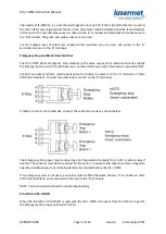
For lasers with dual channel interlocks, use the following connections:
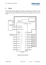
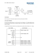
Where the laser may be removed from the system or exchanged a Lasermet Distribution Box may be
used to provide a connection point convenient to the laser. In this case for lasers with a single
channel interlock the A and B ICS-7-OEM output channels are connected in series to pins 1 and 2 of
the plug of the distribution box. See the diagram below.
Leads are available in various lengths to plug into the distribution box. The other end of the lead is
unconnected to allow fitting of a plug suitable for the laser.
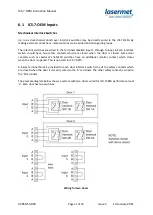
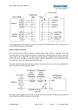
Most industrial lasers are now designed to be compliant with EN 13849-1 and feature two interlock
input channels. This will require a distribution plug and socket with more connections. Furthermore,
some lasers also include one or two ‘laser safe’ contacts which can be monitored by the ICS-7-OEM.
In this instance if either or both ‘laser safe’ contacts are not closed the ICS-7-OEM will not illuminate
the ‘Laser Off’ section of any such warning sign and arming will be inhibited. Depending on the
safety performance of the laser itself such a system could meet EN 13849-1 performance level ‘e’.
The wiring of such a laser is shown below. Please contact Lasermet for assistance with distribution
boxes, connectors and leads if required.
If other devices are using the Output Monitor terminals, for example an LS-20 shutter, all the safe
proving contacts for each channel should be wired in series to the Output Monitor connector such
that the circuit is complete when all devices are in the safe condition.


