Laser Jailer Maintenance Manual
00892-53-000
Page 7 of 16
Issue 2 30 January 2020
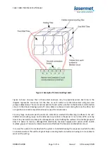
Figure 3. Example of Interconnecting Leads
Figure 3 shows one way that a three-sided enclosure may be physically wired. Each line in the
diagram represents two cores. All the tiles on each surface are interconnected using two-core
jumper cables (blue). The start and end points of each surface are fed to the Monitor and Detection
circuit. In the above drawing a pair of 2-core cables are shown in red coming from each surface, but
a single four-core cable may alternatively be used for convenience.
For very large enclosures patch panels are sometimes used which allow large surfaces to be sub-
divided into smaller groups. Such enclosures may contain a thousand or more tiles. With so many
tiles it may be hard to visually spot a damaged one, so by dividing the surfaces into smaller groups of
tiles it is easier to locate a damaged tile electrically. Lasermet supply patch panels which enable
multiple groups of tiles to be interconnected and fed back the Monitor and Detection circuit.
It is usual for a plan to be made when the system is installed showing the sequence in which the tiles
are interconnected. This will be of great help in locating faults and will save having to remove tiles to
work out the wiring.

