LS-200 Instruction Manual
01297-53-000
Page 7 of 17
Issue 4 19 January 2021
Lasermet also supply extender cables to lengthen the shutter lead.
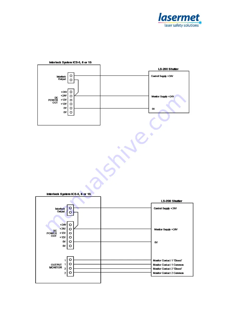
Diagram 1 below shows the usual basic control wiring between a Lasermet ICS-6 Interlock Control
System and LS-200.
Diagram 1. Basic Control Wiring between ICS-6 and LS-200
In this arrangement the shutter buttons are operative allowing the shutter to be opened and closed
when the ICS is armed.
If it is necessary for the shutter to open immediately the ICS is armed, fit a link to connect the
Remote Open Command input to the Control 24V. Make sure the link is not connected to
the Monitor Supply.
Diagram 2 below shows how to implement a SIL-3 / EN13849 PL’e’ safety system using the ‘SIL3’
version of LS-200.
Diagram 2. Implementing a SIL-3 System using ‘SIL3’ LS-200


