Monitored Maglock Instruction Manual
CEB00XXX-53-000
Page 6 of 8
Issue 2 13 January 2020
4
Wiring
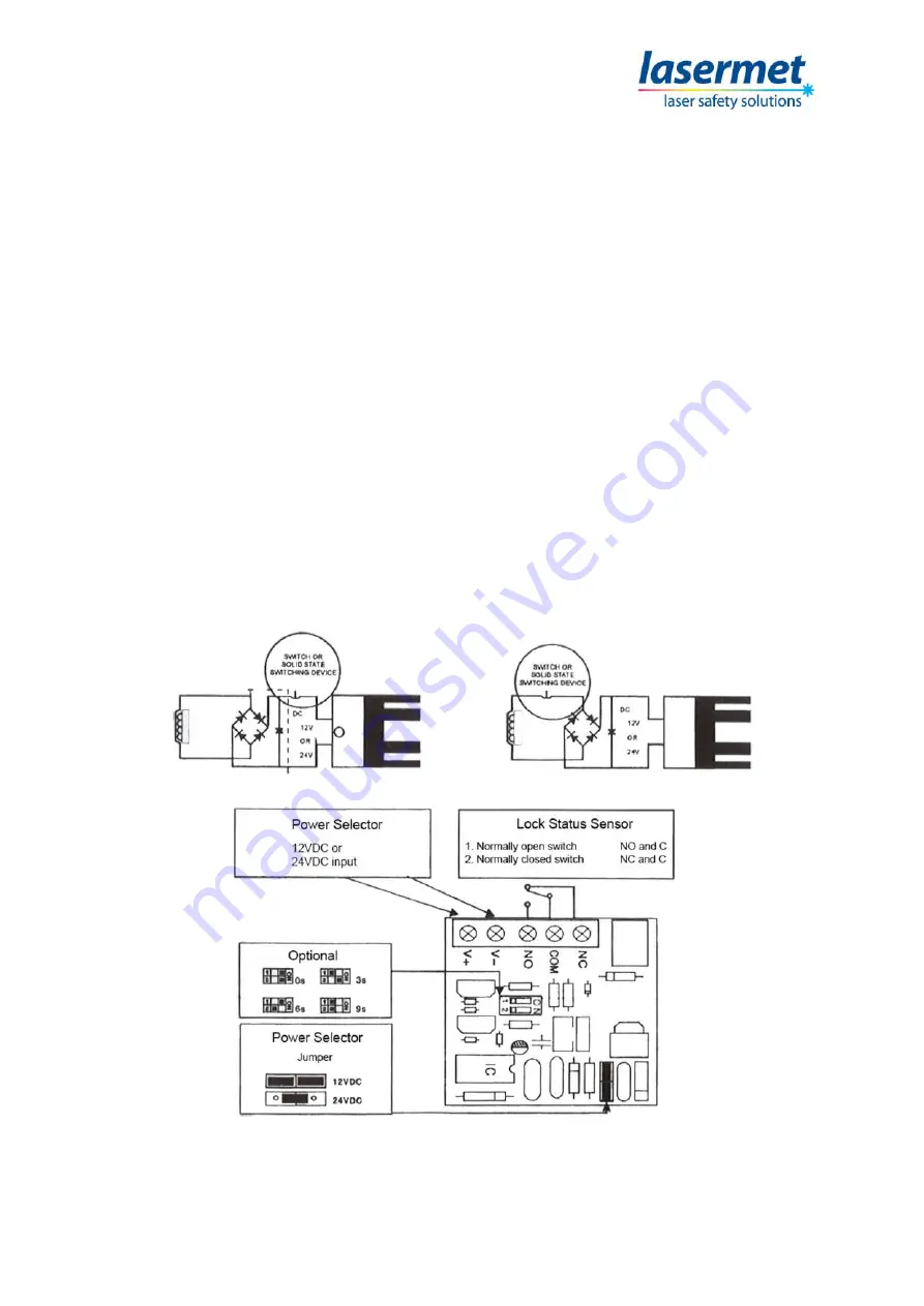
A typical wiring scheme for the Monitored Maglock is shown below. If you require further
assistance, please call Lasermet technical help. Contact details are at the end of this manual.
12VDC Input
Required Power 0.5A minimum
Connect the positive (+) lead from a 12VDC power source to V+
Connect the ground (-) lead from a 12VDC power source to V-
Check jumper for 12VDC operation
24VDC Input
Required Power 0.25A minimum
Connect the positive (+) lead from a 24VDC power source to V+
Connect the ground (-) lead from a 24VDC power source to V-
Check jumper for 24VDC operation
Contacts
Relay dry contacts are rated at 1A at 24VDC for safe operation. Do not exceed this rating.
For a normally open switch, connect the wires from the system to COM and NO.
For a normally closed switch, connect the wires from the system to COM and NC.
NOTE:
If power switch is not wired between DC source voltage and magnet, it will take longer to
de-energize the magnet simulating residual magnetism. See above.


