background image

ii

 (E)

BL55-RU

5. Input/Output Connectors ............................................... 5-1

5-1.

Connectors .................................................................................................... 5-1

5-2.

Connection Specifications ............................................................................ 5-2

5-2-1.

A/B Signal Output Type .............................................................. 5-2

5-2-2.

Analog Output Type .................................................................... 5-4

6. Main Specifications ........................................................ 6-1

7. Dimensions ..................................................................... 7-1

8. Trouble Prevention ......................................................... 8-1

Summary of Contents for BL55-RU

Page 1: ...ons in the manual carefully before use and strictly follow them Keep the manual for future references Lesen Sie die ganze Anleitung vor dem Betrieb aufmerksam durch und folgen Sie beim Betrieb des Geräts den Anweisungen Bewahren Sie diese Bedienungsanleitung zum späferen Nachlesen griffbereit auf ...

Page 2: ...BL55 RU ...

Page 3: ...re operating installing maintaining inspecting repairing or otherwise working on this unit Warning indication meanings The following indications are used throughout this manual and their contents should be under stood before reading the text Warning Failure to observe these precautions may lead to fire electric shock or other accidents resulting in serious injury or death Caution Failure to observ...

Page 4: ... than the specified supply voltages as this may result in fire or electric shock Do not perform installation work with wet hands as this may result in electric shock Do not disassemble or modify the unit as this may result in injury or damage the internal circuits This device is a class 1 laser product using a semiconductor laser with wavelength of 790 nm that is outside the visible range The maxi...

Page 5: ...LLOWING TWO CONDITIONS 1 THIS DEVICE MAY NOT CAUSE HARMFUL INTERFERENCE AND 2 THIS DEVICE MUST ACCEPT ANY INTERFERENCE RECEIVED INCLUDING INTERFERENCE THAT MAY CAUSE UNDESIRED OPERATION r e q w CERTIFICATION PRODUCT COMPLIES WITH DHHS RULES 21 CFR SUBCHAPTER J APPLICABLE AT DATE OF MANUFACTURE Magnescale Co Ltd Shinagawa Intercity Tower A 18F 2 15 1 Konan Minato ku Tokyo 108 6018 Japan MANUFACTURE...

Page 6: ...magnetic interfer ence from other equipment Do not pass the head cable and connection cable through the same duct as the power line Install in a location that is at least 0 5 meters separated from sources of high voltage and large currents and large power relays Notes on attachment location Attach the scale in a location as near as possible to the workpiece and measurement object of the machine Us...

Page 7: ...s Before and during operations be sure to check that our products function properly Provide adequate safety measures to prevent damages in case our products should develop malfunctions Use outside indicated specifications or purposes and modification of our products will void any warranty of the functions and performance as specified of our products When using our products in combination with othe...

Page 8: ...S 003 OPERATION IS SUBJECT TO THE FOLLOWING TWO CONDITIONS 1 THIS DEVICE MAY NOT CAUSE HARMFUL INTERFERENCE AND 2 T H I S D E V I C E M U S T A C C E P T A N Y INTERFERENCE RECEIVED INCLUDING INTERFERENCE THAT MAY CAUSE UNDERSIGNED OPERATION CET APPAREIL NUMERIQUE DE LA CLASSE A EST CONFORME A LA NORME NMB 003 DU CANADA ...

Page 9: ... 4 5 Checking after Installation 3 8 3 4 6 Signal Check 3 9 3 4 7 Checking the Operating Range 3 11 3 4 8 Securing the Head Cable 3 11 3 4 9 Removing the Scale 3 12 3 5 Air Injection Procedure 3 12 3 5 1 Installation 3 12 3 5 2 Air Pressure Source 3 13 3 5 3 Supply Amount 3 13 4 Interface Unit 4 1 4 1 Installing the Interface Unit 4 1 4 2 Removing and Attaching the Interface Unit Cover 4 1 4 3 MOD...

Page 10: ... 5 Input Output Connectors 5 1 5 1 Connectors 5 1 5 2 Connection Specifications 5 2 5 2 1 A B Signal Output Type 5 2 5 2 2 Analog Output Type 5 4 6 Main Specifications 6 1 7 Dimensions 7 1 8 Trouble Prevention 8 1 ...

Page 11: ...or to be disregarded Optical integrated circuits employing the latest semiconductor technology are used to achieve a compact and low energy design Internal non contact structure allows the complete elimination of the causes of errors Maximum speed 3 000 mm s analog output 1 3 Information Specified when Placing Order Reference point position The reference point position is the distance from the mea...

Page 12: ...ket head cap screw M8 25 2 Hex socket head cap screw M4 25 4 Hex socket head cap screw M4 12 2 Hex socket head cap screw M2 6 16 2 Hex socket head cap screw M4 10 6 Spring washer Nominal size 4 4 Plain washer Nominal size 4 2 Hex nut Nominal size 4 2 Spacer t 0 05 2 Spacer t 0 1 3 Cable clamp 2 Hex socket head half union 3 ...

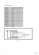
Page 13: ... BL55 047RU 470 mm 0 BL55 052RU 520 mm 1 BL55 057RU 570 mm 1 BL55 062RU 620 mm 1 BL55 072RU 720 mm 1 BL55 077RU 770 mm 1 BL55 082RU 820 mm 1 BL55 087RU 870 mm 1 BL55 092RU 920 mm 1 BL55 102RU 1020 mm 2 Table 1 1 Fig 1 3 Individual number Scale accuracy Output format Shielded type scale with reference point Measuring length cm Model 5 2 5 µm 6 4 5 µm F A B signal output 0 1 0 05 µm G A B signal out...

Page 14: ...1 4 E BL55 RU ...

Page 15: ...is is used when air is injected To inject air remove the hex socket head set screws covering the inlets and then attach the hex socket head half union t Model name and Serial No This indicates the model name and serial number Be sure to always use scale and interface units that have matching serial numbers y Connector Connect the head cable for linking with the interface unit The connector has an ...

Page 16: ...nterface unit is off Be sure to always use scale and interface units that have matching serial numbers e Head cable The head cable connects the scale and interface unit r Input output connectors Scale signals and reference point signals are output when DC 5 V 5 is supplied as the power source Be sure to always use a power supply of DC 5 V 5 The input output connectors have an antistatic cap Do not...

Page 17: ...ment where powder and dust occur install using theA orientation since this allows usage of cutting fluid and prevents the intrusion of cutting dust Install using the B orientation only in other situations when virtually no foreign objects can enter the scale Fig 3 1 Scale installation direction Installing on vertical axis If installing on a machine tool or other equipment where powder and dust occ...

Page 18: ...cal limiting mechanism such as a stopper is needed for machines that exceed the measuring length movable range of the scale Be sure to install this type of device before installing the scale 3 1 3 Protecting the Head Cable The head cable and slider are designed to be attached and removed by screws Be careful not to pull strongly on the cable or repeatedly bend the cable since this can damage it 3 ...

Page 19: ...Cable Clamp For head cable fastening 2 Spacer t 0 05 For slider installation 2 t 0 1 For slider installation 3 Hex socket head half unions For injecting air 3 Plain washers nominal size 4 2 Hex socket head cap screw M4 12 For interface unit 2 In addition to the accessories obtain the following parts and tools Scale installation bracket for sides A and B 1 2 Slider installation bracket for side C 1...

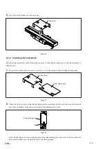
Page 20: ...ad cable whenever carrying these parts Do not carry these parts by holding only onto the head cable Properly ground the scale unit housing slider the interface unit case and power supply frame ground 3 4 Installation Procedure 3 4 1 Head Cable Connection 1 Remove the antistatic connector attached to the slider The antistatic connector can be reused after it is removed and so be careful that you do...

Page 21: ...5 2 pcs 22 N m Screw Tightening torque M4 25 1 or 2 pcs 2 7 N m Washer Spring washers with nominal size 4 1 or 2 washers Measuring length of Side A flatness 0 1 mm 0 0039 or less 70 or 120 mm Side B flatness 0 05 mm 0 0019 or less Parallelism with respect to side A machine runway 0 05 mm 0 0019 or less Parallelism with respect to side B machine runway 0 05 mm 0 0019 or less Measuring length of Sid...

Page 22: ...03 mm 0 00118 or less Parallelism with respect to Side D machine runway 0 05 mm 0 00196 or less Distance between Side B and Side C step 1 0 039 0 1 0 004 mm Distance between Side A and Side D 59 2 323 0 1 0 004 mm Table 3 2 When securing the slider to the mounting bracket be sure to lift the slider side and move the slider above the mounting bracket If the machine is moved to perform positioning t...

Page 23: ...ew Tightening torque M4 25 2 pcs 2 7 N m 3 4 4 Removing the Slider Holder Remove the slider holder after attaching the slider The slider holder can be removed from the slider with a one touch operation There is a protrusion on the scale unit side of the slider The slider holder fits into this protrusion Use the following procedure to remove the slide holder 1 Pull out the slider holder in the leng...

Page 24: ...a checking tool 1 Separate the slider holder removed in section 3 4 4 into the spring holder and slider holding plate Fig 3 11 2 Check that the rib section of the slider holding plate fits smoothly into the space between the scale unit and slider Thickness of the rib section of the slider holding plate 1 mm Fig 3 12 The scale and slider were not attached properly if the slider holding plate does n...

Page 25: ...ace unit 2 Connect the CH2 probe of the oscilloscope to the TP2 and TP7 check pins of the interface unit Fig 3 13 3 Set the TIME DIV switch to the X Y mode 4 Set the deviation sensitivity VOLTS DIV of CH1 and CH2 to 0 5 V DIV 5 Set the input coupling switches of CH1 and CH2 of the oscilloscope to GND and adjust the oscilloscope to locate the signal at the bottom left of the screen 6 Set the input ...

Page 26: ...ignal output type Output format F Amplitude 0 7 Vp p to 1 3 Vp p Output format G Amplitude 0 8 Vp p to 1 2 Vp p Analog output type Output format H Amplitude 0 3 Vp p to 0 6 Vp p The center of the Lissajous figure is 2 5 V If the reference value outputs are not obtained or the center of the Lissajous figure is not at 2 5 V refer to the attached Attaching the Slider see page 3 6 Fig 3 14 Lissajous B...

Page 27: ...attaching the cover of the interface unit Be careful that the scale movement range does not exceed the scale measuring length range of movement If it does the scale can be damaged Fig 3 15 3 4 8 Securing the Head Cable Secure the head cable with a cable clamp so that it does not get in the way of movement or operation The cable clamps are secured using a M4 10 hex socket head cap screw Note that t...

Page 28: ... when it is installed on a machine tool Even when not using a machine tool air should be injected to the scale when installed on machines generating dust or when dust is prevalent in the operating environment 3 5 1 Installation There are a total of three air inlets one each on both sides of the scale unit and on the slider Supply air to all of the air inlets 1 Remove the hex socket head cap screws...

Page 29: ... and regulator to remove any dust mist and other foreign substances Sufficient care should be taken since foreign substances entering inside the scale can cause a breakdown of the scale Fig 3 18 3 5 3 Supply Amount Air should be supplied to the scale at a pressure of 19 6 kPa per scale Note that the pressure of the supply section may be reduced due to the pipe length or layout even if the setting ...

Page 30: ...3 14 E BL55 RU ...

Page 31: ...insert or remove the output connector while power is supplied to the interface unit Fig 4 1 4 2 Removing and Attaching the Interface Unit Cover To set or check the functions remove the four screws and then take off the interface unit cover To attach the interface unit cover tighten the removed screws in their original positions Tightening torque 0 3 N m Be careful not to lose the screws when you r...

Page 32: ...witch 2 Always OFF ON OFF OFF ON ON ON 3 ON B signal is leading Always OFF OFF A signal is leading 4 ON Reverse direction ON Reverse direction OFF Forward direction OFF Forward direction 5 Normally ON Always ON OFF only during reference point adjustment 6 Output format F ON 0 1 µm Output format G ON 0 02 µm Always ON OFF 0 05 µm OFF 0 01 µm 7 ON Outputs reference point signal in single direction o...

Page 33: ...sets 0 1 µm and setting to OFF sets 0 05 µm For G types setting to ON sets 0 02 µm and setting to OFF sets 0 01 µm MODE switch 7 Reference point output selector switch This switch is used to switch the reference point output between single direction and both directions For more information see section 4 4 5 Setting the Reference Point Output and Reference Point Detection Direction MODE switch 8 Al...

Page 34: ...eading ON A B B signal is leading Table 4 2 4 4 2 Changing the Resolution MODE switch 6 resolution setting switch is used to change the resolution of the A B signal output type In the case of output format F ON 0 1 µm In the case of output format G ON 0 02 µm OFF 0 05 µm OFF 0 01 µm 4 4 3 Setting the Reference Point Output Signal Width The width of the reference point output signal can be changed ...

Page 35: ...etting mode and all POS lamps turn off 3 Move the slider the scale unit in the case of scale unit movement in the direction where the reference point is captured and pass through the reference point 4 One of the POS lamps turns on 5 Set MODE switches 1 and 2 reference point POS1 and POS2 switches corresponding to the POS lamps that are on as shown in Table 4 4 POS lamps MODE settings 1 2 OFF OFF O...

Page 36: ...nce point signal in a single direction OFF Outputs reference point signal in both directions However the reference point position is shifted by approximately 4 mm when detecting in the opposite direction from the default reference point detection direction If the switch is set to OFF the procedure is completed Perform the procedure starting from step 2 only if the switch is set to ON 2 Use MODE sw...

Page 37: ...fault setting Hold mode When the scale is in alarm status the alarm status continues to be held even after the element causing the alarm is removed The alarm is reset when the power is turned off and then on again if the cause of the alarm has been cleared MODE switch 8 alarm mode switch Alarm mode OFF Automatic reset mode ON Hold mode Table 4 5 The A B signal is high impedance during the alarm st...

Page 38: ...6 System 1 Load resistance 120 Ω Table 4 6 Note 1 When terminator Z0 120 Ω supply voltage 5 V 5 voltage of load resistance at both ends The level of the output signal is reduced as the scanning frequency increases System 1 A signal output voltage p p value AB signal output average 100 AB signal output average where AB signal output average A signal output voltage p p value B signal output voltage ...

Page 39: ...l output VOZH 2 5 3 4 5 V L level output VOZL 0 0 3 0 5 V Table 4 7 Fig 4 7 Reference point signal and SIN and COS signal phases Item Specifications Min Typ Max Reference point signal width Lz 0 32 µm 0 4 µm 0 48 µm Position of reference point signal edge 0 90 a with respect to SIN signal Table 4 8 Reference point waveform diagram Fig 4 8 REF COS SIN a Center voltage Reference point signal width L...

Page 40: ...4 10 E BL55 RU ...

Page 41: ... is 5 V DC 5 at the input connector to the interface unit 5 V S and 0 V S are for checking the voltage remote sensing function applied to the input connector of the interface unit These voltages can be used to check and control for drops in the supply voltage due to the cables When using a power supply that cannot control power supply fluctuations a power supply input terminal can be used to reduc...

Page 42: ...hared connection the signal ground power supply ground and set the load resistance to 120 Ω Twisted pair cables 1 turn 1 inch min with a core thickness of at least AWG28 are recommended for the differential signal cables It is even better if the characteristic differential impedance is the same as the load resistance value Fig 5 2 Receiving power supplied from the controller Fig 5 3 Send side Send...

Page 43: ...have the same potential To satisfy FCC and EN wrap the ferrite filter TFC 16816 manufactured by KITAGAWA Industries Co LTD one turn around the power supply 5 V ground cable of the A section The system will not be compliant with EN61000 6 2 if the power supply line exceeds 10 m Devise and implement measures to prevent surges Scale Controller 0 V power supply Power supply 5 V Power supply ground A F...

Page 44: ... kΩ REF DS34C86 Example of input circuit 5 2 2 Analog Output Type Fig 5 5 A SIN B Z U0 U0 5 V 5 V S 0 V S 5 V REF REF COS SIN COS GND Sensor circuit Reference example of receive side Scale side Connect to 5 V and GND if there is no remote sensing function GND FG FG Aa U1 Ba U1 Za Z0 R1 R1 R2 R2 Z0 R1 R1 R2 R2 Z0 ...

Page 45: ...or When one of these states occurs the output signal becomes high impedance Output cable length 15 m max Note 4 15 m max Note 3 Note 4 to the trailing electronic control section Grating pitch 1 6 µm Signal pitch 0 4 µm Temperature expansion coefficient 8 10 6 C Protection grade IP53 or equivalent Interface unit IP64 or equivalent when air is injected IP64 or equivalent Vibration resistance 100 m s...

Page 46: ...e length Cable length m Maximum response speed mm s 3 3000 9 2330 15 1660 Note 4 The system will not be compliant with EN61000 6 2 if the power supply line exceeds 10 m Devise and implement measures to prevent surges Note 5 Up to 3 m is available under special specifications However there are some limitations on the maximum response speed according to the cable length For a 3 m cable this is a res...

Page 47: ... BL55 082RU BL55 087RU BL55 092RU BL55 102RU 0 0 000 0 0 000 120 4 724 0 0 000 0 0 000 170 6 693 0 0 000 0 0 000 220 8 661 0 0 000 0 0 000 270 10 630 0 0 000 0 0 000 320 12 598 0 0 000 0 0 000 370 14 567 0 0 000 0 0 000 420 16 535 0 0 000 0 0 000 470 18 504 0 0 000 0 0 000 520 20 472 329 12 953 0 0 000 570 22 441 354 13 937 0 0 000 620 24 409 379 14 921 0 0 000 720 28 346 429 16 890 0 0 000 770 30...

Page 48: ...7 2 E BL55 RU ...

Page 49: ...le damage deformation of the scale unit or other conditions detrimental to the functioning of the scale If any of these events occur immediately stop the machine and contact your Magnescale Co Ltd distributor Depending on the degree of damage some repairs may be unable to be carried out ...

Page 50: ...8 2 E BL55 RU ...

Page 51: ...hme Installation Wartung Inspektion oder Reparatur dieses Gerätes oder der Durchführung anderer Arbeiten durch Bedeutung der Warnhinweise Bei der Durchsicht dieses Handbuchs werden Sie auf die folgenden Hinweise und Symbole stoßen Machen Sie sich mit ihrer Bedeutung vertraut bevor Sie den Text lesen Warnung Eine Missachtung dieser Hinweise kann zu Feuer elektrischen Schlägen oder anderen Unfällen ...

Page 52: ...Schlägen besteht Führen Sie Installationsarbeiten nicht mit nassen Händen aus da hierbei die Gefahr elektrischer Schläge besonders groß ist Unterlassen Sie jeden Versuch das Gerät zu zerlegen oder umzubauen da dies zu Verletzungen oder Beschädigung der internen Schaltungen führen kann Dieses Gerät ist ein Laserprodukt der Klasse 1 Es verwendet einen Halbleiterlaser mit einer Wellenlänge von 790 nm...

Page 53: ...PERATION IS SUBJECT TO THE FOLLOWING TWO CONDITIONS 1 THIS DEVICE MAY NOT CAUSE HARMFUL INTERFERENCE AND 2 THIS DEVICE MUST ACCEPT ANY INTERFERENCE RECEIVED INCLUDING INTERFERENCE THAT MAY CAUSE UNDESIRED OPERATION CERTIFICATION PRODUCT COMPLIES WITH DHHS RULES 21 CFR SUBCHAPTER J APPLICABLE AT DATE OF MANUFACTURE Magnescale Co Ltd Shinagawa Intercity Tower A 18F 2 15 1 Konan Minato ku Tokyo 108 6...

Page 54: ...gskabel nicht durch denselben Kabelkanal wie die Starkstromleitung der Maschine Montieren Sie die Maßstabseinheit an einer Stelle die mindestens 0 5 m Abstand von Hochspannungsquellen Starkstromleitungen und großen Leistungsrelais hat Hinweise zum Anbringungsort Bringen Sie den Maßstab möglichst nahe am Werkstück und Messobjekt der Maschine an Benutzen Sie dieses Produkt nur an Orten mit einer Umg...

Page 55: ...e zu gewährleisten Vergewissern Sie sich vor und während des Betriebs dass das Produkt einwandfrei funktioniert Treffen Sie angemessene Sicherheitsmaßnahmen um im Falle von Funktionsstörungen Schäden zu vermeiden Der Einsatz außerhalb der angegebenen Spezifikationen oder Zwecke und die Modifikation unserer Produkte haben den Verfall der Garantie auf die angegebenen Funktionen und Leistungen unsere...

Page 56: ...S 003 OPERATION IS SUBJECT TO THE FOLLOWING TWO CONDITIONS 1 THIS DEVICE MAY NOT CAUSE HARMFUL INTERFERENCE AND 2 T H I S D E V I C E M U S T A C C E P T A N Y INTERFERENCE RECEIVED INCLUDING INTERFERENCE THAT MAY CAUSE UNDERSIGNED OPERATION CET APPAREIL NUMERIQUE DE LA CLASSE A EST CONFORME A LA NORME NMB 003 DU CANADA ...

Page 57: ...erprüfung nach der Montage 3 8 3 4 6 Signalüberprüfung 3 9 3 4 7 Überprüfung des Bewegungsbereichs 3 11 3 4 8 Sicherung des Kopfkabels 3 11 3 4 9 Demontage des Maßstabs 3 12 3 5 Lufteinblasverfahren 3 12 3 5 1 Montage 3 12 3 5 2 Druckluftquelle 3 13 3 5 3 Luftdruck 3 13 4 Schnittstelleneinheit 4 1 4 1 Montage der Schnittstelleneinheit 4 1 4 2 Abnehmen und Anbringen der Schnittstelleneinheitabdecku...

Page 58: ...RU 5 Ein Ausgangsanschluss 5 1 5 1 Anschluss 5 1 5 2 Anschlussspezifikationen 5 2 5 2 1 A B Signalen Ausgangstyp 5 2 5 2 2 Analogausgangstyp 5 4 6 Technische Daten 6 1 7 Maßzeichnung 7 1 8 Störungsinformation 8 1 ...

Page 59: ... 0 4 µm kann der Interpolationsfehler außer Betracht gelassen werden Nach modernster Halbleitertechnologie gefertigte optische ICs ermöglichen ein kompaktes und energiesparendes Design Die interne kontaktlose Struktur ermöglicht die völlige Ausschaltung von Fehlerursachen Maximale Geschwindigkeit 3 000 mm s analoge Ausgabe 1 3 Bei der Bestellung angegebene Informationen Bezugspunktposition Die Bez...

Page 60: ...nensechskantschraube M8 25 2 Innensechskantschraube M4 25 4 Innensechskantschraube M4 12 2 Innensechskantschraube M2 6 16 2 Innensechskantschraube M4 10 6 Federscheiben Nennmaß 4 4 Unterlegscheiben Nennmaß 4 2 Sechskantmuttern Nennmaß 4 2 Abstandsstück t 0 05 2 Abstandsstück t 0 1 3 Kabelhalter 2 Innensechskantverbindungen 3 ...

Page 61: ...55 047RU 470 mm 0 BL55 052RU 520 mm 1 BL55 057RU 570 mm 1 BL55 062RU 620 mm 1 BL55 072RU 720 mm 1 BL55 077RU 770 mm 1 BL55 082RU 820 mm 1 BL55 087RU 870 mm 1 BL55 092RU 920 mm 1 BL55 102RU 1020 mm 2 Tabelle 1 1 Abb 1 3 K BL55 RU Individuelle Nummer Maßstabsgenauigkeit Ausgabeformat Abgeschirmter Maßstab mit Bezugspunkt Messlänge cm Modell 5 2 5 µm 6 4 5 µm F A B Signalausgabe 0 1 0 05 µm G A B Sig...

Page 62: ...1 4 G BL55 RU ...

Page 63: ...sechskant Zylinderkopfschrauben welche die Einlässe verschließen entfernen und dann die Innensechskantverbindung anbringen t Modellbezeichnung und Seriennummer An dieser Stelle sind Modellbezeichnung und Seriennummer angegeben Achten Sie darauf dass die Seriennummern der verwendeten Maßstabs und Schnittstelleneinheit übereinstimmen y Anschluss Hier wird das Kopfkabel für die Verbindung mit der Sch...

Page 64: ... Achten Sie darauf dass die Seriennummern der verwendeten Maßstabs und Schnittstelleneinheit übereinstimmen e Kopfkabel Das Kopfkabel verbindet den Maßstab mit der Schnittstelleneinheit r Ein Ausgangsanschluss Eine Gleichstromspeisung von 5 V 5 über den Ein Ausgangsanschluss wird für die Ausgabe der Maßstabssignale und des Bezugspunktsignals verwendet Verwenden Sie stets eine Gleichstromversorgung...

Page 65: ...den die Pulver oder Staub erzeugt verwenden Sie die Ausrichtung A weil dann der Einsatz von Schneidflüssigkeit möglich ist und das Eindringen von Schneidstaub verhindert wird Verwenden Sie die Ausrichtung B nur in anderen Situationen wenn das Eindringen von Fremdkörpern in den Maßstab praktisch ausgeschlossen ist Abb 3 1 Maßstab Montagerichtungen Montage an einer vertikalen Achse Soll die Maßstabs...

Page 66: ...ür Maschinen welche die Messlänge Bewegungsbereich der Maßstab überschreiten wird ein mechanischer Begrenzungsmechanismus z B ein Anschlag benötigt Installieren Sie eine derartige Vorrichtung unbedingt vor der Anbringung der Maßstab 3 1 3 Schutz des Kopfkabels Kopfkabel und Schieber sind für die Befestigung mit Schrauben ausgelegt Unterlassen Sie starkes Ziehen am Kopfkabel oderAufwickeln Dadurch ...

Page 67: ...Schiebers 2 t 0 1 Zur Befestigung des Schiebers 3 Innensechskantverbindungen Für Lufteinblasung 3 Unterlegscheiben Nennmaß 4 2 Innensechskantschraube M4 12 Für Schnittstelleneinheit 2 Neben den Zubehörteilen werden die folgenden Teile und Werkzeuge benötigt Halter zur Befestigung des Maßstabs der Fläche A B entsprechendes Teil 1 bis 2 Halter zur Befestigung des Schiebers der Fläche C entsprechende...

Page 68: ...Kopfkabels Nehmen Sie eine Erdung für das Gehäuse der Maßstabseinheit und den Schieberteil sowie für die Rahmenmasse des Schnittstelleneinheitgehäuses und die Stromversorgung vor 3 4 Montageverfahren 3 4 1 Anschließen des Kopfkabels 1 Entfernen Sie den am Schieber angebrachten Antistatikstecker Da der abgenommene Antistatikstecker wiederverwendet werden kann achten Sie darauf dass er nicht verlore...

Page 69: ...rwendete Schrauben Anzugsmoment M4 25 1 oder 2 Schrauben 2 7 N m Verwendete Unterlegscheiben Federscheiben von Nennmaß 4 1 oder 2 Scheiben Messlänge von 70 oder 120 mm Ebenheit der Fläche A max 0 1 mm Ebenheit der Fläche B max 0 05 mm Parallelität in Bezug auf die Maschinenbewegung an Fläche A max 0 05 mm Parallelität in Bezug auf die Maschinenbewegung an Fläche B max 0 05 mm Messlänge von 170 mm ...

Page 70: ...aschinenbewegung an Fläche C max 0 03 mm Parallelität in Bezug auf die Maschinenbewegung an Fläche D max 0 05 mm Abstand zwischen Fläche B und Fläche C Stufe 1 0 1 mm Abstand zwischen Fläche A und Fläche D 59 0 1 mm Tabelle 3 2 Wenn Sie den Schieber am Montagehalter befestigen müssen Sie den Schieber anheben und über den Montagehalter bewegen Falls die Maschine zur Durchführung der Positionierung ...

Page 71: ...tmuttern mit Nennmaß 4 2 Muttern Verwendete Schrauben Anzugsmoment M4 25 2 Schrauben 2 7 N m 3 4 4 Entfernen des Schieberhalters Entfernen Sie den Schieberhalter nach der Anbringung des Schiebers Der Schieberhalter kann mit einem Handgriff vom Schieber abgenommen werden Der Schieber weist auf der Seite der Maßstabseinheit einen Vorsprung auf Dieser dient zur Befestigung des Schieberhalters Entfern...

Page 72: ...ters als Prüfwerkzeug 1 Zerlegen Sie den inAbschnitt 3 4 4 entfernten Schieberhalter in Schieberhalter und Schieberhalteplatte Abb 3 11 2 Prüfen Sie ob der Rippenteil der Schieberhalteplatte einwandfrei in den Spalt zwischen Maßstabseinheit und Schieber passt Dicke des Rippenteils der Schieberhalteplatte 1 mm Abb 3 12 Maßstab und Schieber sind nicht richtig montiert wenn die Schieberhalteplatte ni...

Page 73: ... Y MODE 4 Stellen Sie die Deviationsempfindlichkeit VOLTS DIV von CH1 und CH2 auf 0 5 V DIV ein 5 Stellen Sie die Eingangskopplungsschalter von CH1 und CH2 am Oszilloskop auf GND und stellen Sie das Oszilloskop so ein dass das Signal in Bildschirmmitte angezeigt wird 6 Stellen Sie die Eingangskopplungsschalter von CH1 und CH2 am Oszilloskop auf DC 7 Schalten Sie die Stromzufuhr der Schnittstellene...

Page 74: ... Werte Typ mit A B Signalausgabe Ausgabeformat F Amplitude 0 7 Vs s bis 1 3 Vs s Ausgabeformat G Amplitude 0 8 Vs s bis 1 2 Vs s Typ mit Analogausgabe Ausgabeformat H Amplitude 0 3 Vs s bis 0 6 Vs s Die Mitte der Lissajousfigur entspricht 2 5 V Falls die Bezugswertausgaben nicht erzielt werden oder die Mitte der Lissajousfigur 2 5V nicht entspricht sehen Sie auf der Seite 3 6 Montage des Schiebers...

Page 75: ...g der Schnittstelleneinheit finden Sie in Abschnitt 4 2 Achten Sie dabei darauf dass der Bewegungsbereich nicht die Messlänge und den Bewegungsbereich des Maßstabs überschreitet Anderenfalls kann der Maßstab beschädigt werden Abb 3 15 3 4 8 Sicherung des Kopfkabels Sichern Sie das Kopfkabel mit den Kabelhaltern so dass es die Bewegung oder den Betrieb nicht behindert Die Kabelhalter werden mit ein...

Page 76: ...ner Werkzeugmaschine angebracht ist Selbst wenn keine Werkzeugmaschine verwendet wird sollte Luft in den Maßstab eingeblasen werden wenn er an Maschinen angebracht wird die Staub erzeugen oder wenn Staub in der Betriebsumgebung vorwiegt 3 5 1 Montage Es sind insgesamt drei Lufteinlässe vorhanden jeweils einer auf beiden Seiten der Maßstabseinheit und am Schieber Führen Sie Luft zu diesen Lufteinlä...

Page 77: ...n Staub Feuchtigkeit und anderen Fremdkörpern zu befreien Dabei sollte ausreichende Sorgfalt angewandt werden da in den Maßstab eindringende Fremdkörper eine Störung des Maßstabs verursachen können Abb 3 18 3 5 3 Luftdruck Die dem Maßstab zugeführte Luft sollte einen Druck von 19 6 kPa pro Maßstab haben Beachten Sie dass der Druck auf der Zufuhrseite durch die Rohrlänge oder die Anordnung reduzier...

Page 78: ...3 14 G BL55 RU ...

Page 79: ...schlusses bei eingeschalteter Stromversorgung der Schnittstelleneinheit Abb 4 1 4 2 Abnehmen und Anbringen der Schnittstelleneinheitabdeckung Um die Funktionen einzustellen oder zu überprüfen entfernen Sie die vier Schrauben und nehmen Sie dann die Schnittstelleneinheitabdeckung ab Um die Schnittstelleneinheitabdeckung wieder anzubringen drehen Sie die entfernten Schrauben wieder an den ursprüngli...

Page 80: ...2 Immer OFF ON OFF OFF ON ON ON 3 ON Voreilung des B Signals Immer OFF OFF Voreilung des A Signals 4 ON Rückwärtsrichtung ON Rückwärtsrichtung OFF Vorwärtsrichtung OFF Vorwärtsrichtung 5 Normalerweise ON Immer ON OFF nur während der Bezugspunkteinstellung 6 Ausgabeformat F ON 0 1 µm Ausgabeformat G ON 0 02 µm Immer ON OFF 0 05 µm OFF 0 01 µm 7 ON Das Bezugspunktsignal wird nur in einer Richtung au...

Page 81: ... auf ON 0 1 µm und bei Einstellung auf OFF 0 05 µm Für G Typen erhält man bei Einstellung auf ON 0 02 µm und bei Einstellung auf OFF 0 01 µm MODE Schalter 7 Bezugspunktausgabe Wahlschalter Dieser Schalter dient zum Umschalten zwischen Bezugspunktausgabe in einer Richtung und in beiden Richtungen Weitere Informationen dazu in Abschnitt 4 4 5 Einstellung der Bezugspunktausgabe und der Bezugspunkterk...

Page 82: ...ung des A Signals ON A B Voreilung des B Signals Tabelle 4 2 4 4 2 Ändern der Auflösung Der MODE Schalter 6 Auflösungs Einstellschalter wird zum Ändern der Auflösung des A B Signalen Ausgangstyps verwendet Im Falle der Ausgabeform F ON 0 1 µm Im Falle der Ausgabeform G ON 0 02 µm OFF 0 05 µm OFF 0 01 µm 4 4 3 Einstellen der Bezugspunkt Ausgangssignalbreite Analogausgangstyp Immer mit der Einstellu...

Page 83: ...e POS Lampen sind erloschen 3 Bewegen Sie den Schieber die Maßstabseinheit im Falle einer Bewegung der Maßstabseinheit in die Richtung in welcher der Bezugspunkt erfasst wird und gehen Sie durch den Bezugspunkt 4 Eine der POS Lampen leuchtet auf 5 Stellen Sie die MODE Schalter 1 und 2 Bezugspunktschalter POS1 und POS2 in Übereinstimmung mit den leuchtenden POS Lampen ein wie in Tabelle 4 4 gezeigt...

Page 84: ...iner Richtung ausgegeben OFF Das Bezugspunktsignal wird in beiden Richtungen ausgegeben Bei Erkennung in der entgegengesetzten Richtung von der Standard Bezugspunkterkennungsrichtung verschiebt sich die Bezugspunktposition jedoch um ca 4 mm Wenn der Schalter auf OFF gestellt wird ist das Verfahren beendet Führen Sie das Verfahren nur dann ab Schritt 2 durch wenn der Schalter auf ON gestellt wird 2...

Page 85: ...modus Befindet sich der Maßstab im Alarmzustand bleibt der Alarmzustand auch nach der Beseitigung der Alarmursache weiter aufrechterhalten Nachdem die Alarmursache beseitigt worden ist wird der Alarm zurückgesetzt sobald die Stromversorgung aus und wieder eingeschaltet worden ist MODE Schalter 8 Alarmmodusschalter Alarmmodus OFF Modus für automatische Zurücksetzung ON Haltemodus Tabelle 4 5 Das A ...

Page 86: ... Tabelle 4 6 Hinweis 1 Wenn Abschlusswiderstand Z0 120 Ω Versorgungsspannung 5 V 5 Spannung des Lastwiderstands an beiden Enden Der Pegel des Ausgangssignals reduziert sich mit zunehmender Abtastfrequenz System 1 s s Wert der A Signalen Ausgangsspannung AB Signalen Ausgangsdurchschnitt 100 AB Signalen Ausgangsdurchschnitt wobei AB Signalen Ausgangsdurchschnitt s s Wert der A Signalen Ausgangsspann...

Page 87: ...nstand Symbol Spezifikationen Einheit Min Typ Max H Pegel Ausgang VOZH 2 5 3 4 5 V L Pegel Ausgang VOZL 0 0 3 0 5 V Tabelle 4 7 Abb 4 7 Bezugspunktsignal sowie SIN und COS Signalphasen Gegenstand Spezifikationen Min Typ Max Bezugspunktsignalbreite Lz 0 32 µm 0 4 µm 0 48 µm Position der Bezugspunktsignalflanke a 0 90 im Hinblick auf das SIN Signal Tabelle 4 8 Konzeptdiagramm der Bezugspunkt Wellenf...

Page 88: ...4 10 G BL55 RU ...

Page 89: ...om 5 beträgt 5 V S und 0 V S dienen zur Überprüfung der an den Eingangsanschluss der Schnittstelleneinheit angelegten Spannung Fernabtastfunktion Diese Spannungen können verwendet werden um einen Abfall der Versorgungsspannung durch die Kabel zu überprüfen und zu regulieren Wenn eine Stromquelle verwendet wird die nicht in der Lage ist Spannungsschwankungen zu regulieren kann eine Stromquellen Ein...

Page 90: ...en eine Signalerde Stromquellenerde gemeinsamer Anschluss anzuschließen und den Lastwiderstand auf 120 Ω einzustellen Verdrillte Doppelleitungen min 1 Umdrehung 1 Zoll mit einer Kerndicke von mindestens AWG28 werden für die Differentialsignalkabel empfohlen Es ist sogar noch besser wenn die Differential Kennimpedanz mit dem Lastwiderstandswert identisch ist Abb 5 2 Bei Empfang der Stromversorgung ...

Page 91: ...gleiche Potential Um dieVorschriften von FCC und EN zu erfüllen wickeln Sie den von KITAGAWA Industries Co LTD hergestellten Ferritfilter TFC 16816 imAbschnitt A eine Umdrehung um das Stromversorgungskabel 5 V Erde Das System erfüllt nicht die Vorschrift EN61000 6 2 wenn die Stromversorgungsleitung länger als 10 m ist Treffen Sie Maßnahmen zur Verhütung von Spannungsstößen Maßstab Steuergerät 0 V ...

Page 92: ...34C86 Beispiel der Eingangsschaltung 5 2 2 Analogausgangstyp Abb 5 5 A B Z U0 U0 0 V S GND Sensorschaltung Musterbeispiel der Empfängerseite Maßstabsseite An 5 V und Erde anschließen wenn keine Fernabtastfunktion vorhanden ist GND FG FG Aa U1 Ba U1 Za Z0 R1 R1 R2 R2 Z0 R1 R1 R2 R2 Z0 SIN 5 V 5 V S 5 V REF REF COS SIN COS ...

Page 93: ...alpegelfehler Wenn einer dieser Zustände auftritt hat das Ausgangssignal hohe Impedanz Ausgangskabellänge max 15 m Hinweis 4 max 15 m Hinweis 3 Hinweis 4 bis zum nachfolgenden elektronischen Steuerteil Gitterteilung 1 6 µm Signalteilung 0 4 µm Wärmeausdehnungskoeffizient 8 10 6 C Schutzklgrad IP53 oder Entsprechung Schnittstelleneinheit IP64 oder bei Lufteinblasung Entsprechung IP64 oder Entsprech...

Page 94: ...gangskabellänge Kabellänge m Maximale Ansprechgeschwindigkeit mm s 3 3000 9 2330 15 1660 Hinweis 4 Das System erfüllt nicht die Vorschrift EN61000 6 2 wenn die Stromversorgungsleitung länger als 10 m ist Treffen Sie Maßnahmen zur Verhütung von Spannungsstößen Hinweis 5 Eine Länge von bis zu 3 m ist auch als Sonderspezifikationen erhältlich Je nach der Kabellänge gibt es jedoch Einschränkungen der ...

Page 95: ...5 047RU BL55 052RU BL55 057RU BL55 062RU BL55 072RU BL55 077RU BL55 082RU BL55 087RU BL55 092RU BL55 102RU 0 0 120 0 0 170 0 0 220 0 0 270 0 0 320 0 0 370 0 0 420 0 0 470 0 0 520 329 0 570 354 0 620 379 0 720 429 0 770 454 0 820 479 0 870 504 0 920 529 0 1020 386 385 Hinweis 2 M M M M 0 1 0 05 0 05 0 05 0 1 0 1 Hinweis 1 Messlänge L Modell F1 F2 0 05 0 03 M 0 03 0 02 1 1 0 1 Einheit mm Hinweis 1 B...

Page 96: ...7 2 G BL55 RU ...

Page 97: ...die Maßstabseinheit verformt wird oder eine andere Situation eintritt die schädlich für die Funktion des Maßstabs ist Halten Sie sofort die Maschine an und kontaktieren Sie dann eine Magnescale Co Ltd Kundendienststelle oder Ihre lokale Werkstatt Bei besonders großem Schadensausmaß kann eine Reparatur unmöglich sein ...

Page 98: ...8 2 G BL55 RU ...

Page 99: ...priété de Magnescale Co Ltd et sont destinées exclusivement à l usage des acquéreurs de l équipement décrit dans ce manuel Magnescale Co Ltd interdit formellement la copie de quelque partie que ce soit de ce manuel ou son emploi pour tout autre but que des opérations ou entretiens de l équipement à moins d une permission écrite de Magnescale Co Ltd Die in dieser Anleitung enthaltenen Informationen...

Page 100: ...2010 4 Printed in Japan 2002 Magnescale Co Ltd BL55 RU 2 917 853 18 Shinagawa Intercity Tower A 18F 2 15 1 Konan Minato ku Tokyo 108 6018 Japan ...

Reviews: