3-6
(E)
BL55-RU
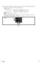
3-4-3. Attaching the Slider
Parallelism/flatness of alignment surface
Fig. 3-7
Attach the slider so that the parallelism and flatness of the alignment surface are as shown in Table 3-2.
Screw/Washer: ............... M4
×
25: 2 pcs. / Spring washers with nominal size 4: 2 washers
Tightening torque: ......... 2.7 N
·
m
Side C parallelism
0.02 mm (0.00078") or less
Side D parallelism
0.05 mm (0.00196") or less
Parallelism with respect to Side C machine runway
0.03 mm (0.00118") or less
Parallelism with respect to Side D machine runway
0.05 mm (0.00196") or less
Distance between Side B and Side C (step)
1 (0.039")
±
0.1 (0.004") mm
Distance between Side A and Side D
59 (2.323")
±
0.1 (0.004") mm
Table 3-2
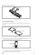
When securing the slider to the mounting bracket, be sure to lift the slider side and move the slider above the
mounting bracket. If the machine is moved to perform positioning, the slider will contact the mounting
bracket, and this can damage the scale unit.
61.5 (2.421")
±
0.1 (0.004")
A (alignment surface)
B (alignment surface)
Scale unit
C (alignment surface)
D (alignment surface)
Unit: mm (inch)
Slider unit
1 (0.039")
±
0.1 (0.004")
Summary of Contents for BL55-RU
Page 2: ...BL55 RU ...
Page 14: ...1 4 E BL55 RU ...
Page 30: ...3 14 E BL55 RU ...
Page 40: ...4 10 E BL55 RU ...
Page 48: ...7 2 E BL55 RU ...
Page 50: ...8 2 E BL55 RU ...
Page 62: ...1 4 G BL55 RU ...
Page 78: ...3 14 G BL55 RU ...
Page 88: ...4 10 G BL55 RU ...
Page 96: ...7 2 G BL55 RU ...
Page 98: ...8 2 G BL55 RU ...


