4-4
(E)
BL55-RU
4-4. Changing the Settings
For analog output types, only make the settings in section 4-4-5, “Setting the Reference Point Output and
Reference Point Detection Direction.” Always use the settings in Table 4-1 for analog output types, except
for the settings in section 4-4-5, “Setting the Reference Point Output and Reference Point Detection Direction.”
4-4-1. Changing the Direction
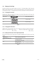
MODE switch 3 (Direction switch) is used to change the positional relationship of the A/B signal with
respect to the scale movement direction.
MODE switch 3
Moves to head cable side
OFF
A
B
A signal is leading
ON
A
B
B signal is leading
Table 4-2
4-4-2. Changing the Resolution
MODE switch 6 (resolution setting switch) is used to change the resolution of the A/B signal output type.
In the case of output format F: ON = 0.1
µ
m
In the case of output format G: ON = 0.02
µ
m
OFF = 0.05
µ
m
OFF = 0.01
µ
m
4-4-3. Setting the Reference Point Output Signal Width
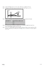
The width of the reference point output signal can be changed by MODE switch 10 (reference point mode
switch).
MODE switch 10
Reference point output signal width
(reference point mode switch)
ON
1/4 reference point mode
The reference point signal is output in synchronization when both the
A and B signal are at the high level.
OFF
Reference point mode
The reference point signal is output in synchronization during the one
cycle of the A signal.
Table 4-3
Summary of Contents for BL55-RU
Page 2: ...BL55 RU ...
Page 14: ...1 4 E BL55 RU ...
Page 30: ...3 14 E BL55 RU ...
Page 40: ...4 10 E BL55 RU ...
Page 48: ...7 2 E BL55 RU ...
Page 50: ...8 2 E BL55 RU ...
Page 62: ...1 4 G BL55 RU ...
Page 78: ...3 14 G BL55 RU ...
Page 88: ...4 10 G BL55 RU ...
Page 96: ...7 2 G BL55 RU ...
Page 98: ...8 2 G BL55 RU ...


