BL57-NE
(E)
3-11
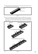
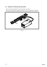
Check for interference
Bring directly against
Scale
Detector head
Stopper
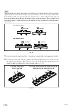
Azimuth direction
Azimuth direction
Stopper
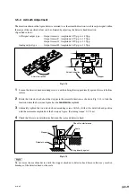
3-5-2. Azimuth Adjustment
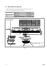
The direction shown in the figure below is referred to as the azimuth direction. A stable output signal within
the range of the specified values can be obtained by adjusting the detector head direction.
<Specified values>
A/B signal output type ...... Output format A : Amplitude 0.9 Vp-p to 1.8 Vp-p
Output format F : Amplitude 0.7 Vp-p to 1.3 Vp-p
Output format G : Amplitude 0.8 Vp-p to 1.2 Vp-p
Analog output type ........... Output format H : Amplitude 0.6 Vp-p to 1.1 Vp-p
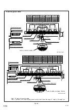
Fig. 3-14
1
Loosen the detector head mounting screws, and then bring the stopper directly against the scale bottom
surface.
2
Rotate the detector head about the stopper in the azimuth direction as shown in Fig. 3-14 to find the
location where the Lissajous’ figure has the
maximum
amplitude.
3
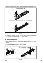
Alternately tighten the two detector head mounting screws little by little at the detector head position
with the maximum amplitude of the Lissajous’ figure. (Fastening torque: 0.3 N
·
m)
4
Check that there is no interference between the scale and detector head.
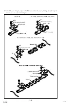
Fig. 3-15
Do not move the machine device with the stopper attached to detector head because this may result in
breakage of the detector head or the scale.
Summary of Contents for BL57-003NE Series
Page 2: ...BL57 NE...
Page 8: ...6 E BL57 NE...
Page 10: ...ii E BL57 NE...
Page 14: ...2 2 E BL57 NE...
Page 28: ...BL57 NE 3 14 E...
Page 36: ...4 8 E BL57 NE...
Page 48: ...7 4 E BL57 NE...
Page 50: ...8 2 E BL57 NE...
Page 58: ...ii G BL57 NE...
Page 62: ...2 2 G BL57 NE...
Page 76: ...BL57 NE 3 14 G...
Page 84: ...4 8 G BL57 NE...
Page 96: ...7 4 G BL57 NE...
Page 98: ...8 2 G BL57 NE...

